Picking the wrong heat transfer fluid doesn’t announce itself dramatically — it shows up as a fouled heat exchanger at the worst possible moment, a batch that ran 15°C hotter than setpoint, or a pump seal that failed six months into what should have been a three-year service interval. In forced-circulation thermal systems, fluid selection is quietly one of the highest-leverage decisions on the plant floor, yet it often gets delegated to whoever ordered the fluid last time. The financial exposure is real: unplanned downtime in a continuous process can run anywhere from a few thousand to tens of thousands per day depending on the line, and thermal fluid degradation rarely gives you much warning before it becomes a production problem.
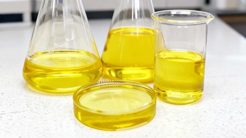
Silicone oil — typically polydimethylsiloxane (PDMS) — suits heat transfer applications requiring a service range of roughly -60°C to +300°C continuous, with short excursions to around +350°C. Viscosity grade drives pump sizing and heat transfer coefficient; 50–100 cSt at 25°C covers most forced-circulation systems. Thermal conductivity runs 0.15–0.20 W/(m·K), modestly better than mineral oil. The right grade depends on your operating temperature, flow regime, and whether the system sits idle in cold climates.
What makes silicone oil genuinely interesting — and genuinely tricky to specify — is that its properties don’t behave the way most engineers expect coming from a mineral oil background. The viscosity-temperature curve is flatter, the oxidative stability ceiling is higher, but the thermal conductivity is still low enough that getting the flow velocity wrong will hurt you more than the fluid choice itself. Understanding those trade-offs before you write the purchase order is what separates a system that runs cleanly for years from one that has you back on the phone with your fluid supplier inside eighteen months.
Decoding the Silicone Oil Product Spectrum: PDMS, Phenyl, and Fluorosilicone Variants Explained
The label “silicone oil” covers a surprisingly wide range of chemistries, and conflating them at the selection stage is one of the more expensive mistakes a procurement team can make. Getting clear on the product families first — before you look at a single datasheet viscosity number — saves time and rules out a lot of wrong purchases.
Polydimethylsiloxane: The Baseline Chemistry
PDMS is the workhorse. The backbone is a repeating Si–O–Si chain with two methyl groups on each silicon atom, and virtually everything about the fluid’s behavior follows from how long that chain is. Short chains mean low molecular weight, low viscosity, and high vapor pressure. Hexamethyldisiloxane sits at the bottom of the range, around 0.65 cSt — too volatile for any serious recirculating heat transfer system. As chain length increases, viscosity climbs from the low single digits through 50, 100, 350, and up past 60,000 cSt at 25°C.
For forced-circulation heat transfer, the practically useful window is roughly 5–350 cSt. Below 5 cSt, vapor losses at elevated temperature become a real operational nuisance and the flash point drops uncomfortably low. Above 350 cSt, you’re fighting pump head requirements and poor film-side heat transfer coefficients — the fluid moves heat adequately in a bench test but struggles in real tubular or plate exchangers where velocity matters. The 50–100 cSt range dominates most industrial installations because it balances pumpability, film coefficient, and acceptable vapor pressure across a broad temperature window.
PDMS handles continuous service up to roughly 200–230°C in well-designed, oxygen-limited systems. Push it much harder and thermal cracking and oxidative degradation accelerate, producing volatile low-MW fragments and a gummy residue that will foul your heat exchanger surfaces faster than you’d expect.
Phenyl-Modified Silicones: When You Need More Temperature
Substituting phenyl groups — either as diphenyl or methylphenyl arrangements — into the siloxane backbone changes the thermal stability picture substantially. The bulkier aromatic ring structures inhibit backbone scission at elevated temperatures, extending the credible continuous service ceiling to 280–300°C, with short excursions tolerable to around 350°C depending on system design and oxygen exclusion quality.
Dow’s Syltherm 800 and Shin-Etsu’s KF-54 are the products most engineers encounter in this segment. Both are well-characterized fluids with long field histories in pharmaceutical reactors, semiconductor process equipment, and solar thermal collectors. The tradeoff is real, though: phenyl-modified fluids carry a higher pour point than PDMS equivalents (KF-54, for instance, solidifies around 24°C, which means heat tracing on outdoor piping in cold climates is not optional), and they typically cost 2–4x more per liter depending on volume and source. That cost premium is usually justified when you actually need the temperature range; it’s wasteful when a 150°C process gets specified with phenyl fluid because the engineer was being cautious.
Phenyl-modified silicone oils offer meaningfully better thermal stability above 200°C compared to PDMS gradesTrue
The aromatic phenyl substituents on the siloxane backbone resist thermal oxidation at higher temperatures, which is well-documented in fluid supplier technical literature and independently supported by thermal aging studies showing lower viscosity drift and deposit formation rates in phenyl fluids operated above 220°C.
Fluorosilicone: Niche Tool, Not a General Solution
Fluorosilicone fluids replace some methyl groups with trifluoropropyl substituents, giving them remarkable resistance to hydrocarbon solvents, fuels, and some aggressive chemicals. In a system where the heat transfer loop has a meaningful probability of contamination with jet fuel or chlorinated solvents, fluorosilicone is worth the conversation.
For pure heat transfer duty with clean process fluids, they are almost never the right answer. Expect to pay roughly 4–8x the cost of a comparable PDMS grade, depending on viscosity and order volume. Thermal performance is not superior to PDMS — fluorosilicones actually run slightly lower thermal conductivity — and the upper service temperature is no better. The cost is paying for chemical inertness you probably don’t need.
The Grade Confusion Problem: Heat Transfer vs. Release Agent vs. Cosmetic
This catches people out more than it should. PDMS used in mold release, textile softeners, and personal care products shares the same base chemistry as heat transfer fluid. A procurement team under cost pressure may find an apparently identical 100 cSt PDMS at a lower price from a non-industrial supplier.
The difference is in the additive and stabilizer package. Heat transfer grades carry antioxidants, metal deactivators, and sometimes corrosion inhibitors formulated to survive thousands of operating hours at elevated temperature. Release agent and cosmetic grades carry none of that — or carry additives optimized for entirely different performance criteria. Run the wrong grade through a 250°C system and you’ll see oxidative deposits forming on heat exchanger walls within a few hundred hours. In practice, those deposits cut heat transfer coefficients, increase pressure drop, and eventually require a chemical clean that costs far more than the price difference on the drum.
Always verify the fluid is explicitly designated for heat transfer service on the technical datasheet, not just described as “heat transfer compatible” by a distributor trying to move inventory.
Quick Selection Framework
| Max Operating Temp | Radiation Exposure | Chemical Contamination Risk | Fluid Family to Evaluate |
|---|---|---|---|
| Below 200°C | No | Low | PDMS, 50–350 cSt |
| 200–300°C | Possible | Low | Phenyl-modified (e.g., Syltherm 800, KF-54) |
| Above 300°C | Any | Low | Vapor-phase organics or alternative fluid; silicone rarely appropriate |
| Any range | No | High (solvents/fuels) | Fluorosilicone — verify cost is justified |
Get the chemistry family right before you spend time comparing viscosity grades. It’s a coarser cut, but it’s the one that prevents the expensive re-specification six months into commissioning.
Viscosity Selection: Matching Flow Regime, Pump Curve, and Heat Transfer Coefficient to Your System
Viscosity is the one spec that will make or break your silicone oil system before you ever think about thermal stability or compatibility. Get it wrong and you’re either cavitating your pump on a cold Monday morning or running laminar flow through a jacketed reactor that needs turbulent convection to hit its process duty. Neither failure is obvious until you’re already in trouble.
The Core Trade-Off: Why There’s No Single “Best” Grade
Lower viscosity fluids give you higher Reynolds numbers at a given velocity, which pushes you deeper into turbulent flow and raises the convective film coefficient h — in fully turbulent pipe flow, h scales roughly with Re^0.8, so the gains compound quickly as Re climbs above 10,000. A 50 cSt fluid will typically run at two to three times the Re of a 100 cSt fluid under identical pipe geometry and flow velocity.
The catch: low-viscosity grades thin out aggressively at elevated temperatures (though silicones are far better than mineral oil on this front), and at cold startup, even a nominally “low” viscosity grade can become a near-solid in the pump suction. Pump seal lubrication also suffers with very thin fluids. The practical optimum for most forced-circulation systems lands in the 50–100 cSt range at 25°C, but that’s a starting point, not a rule.
Worked Example: Jacketed Vessel, 10 kW Duty
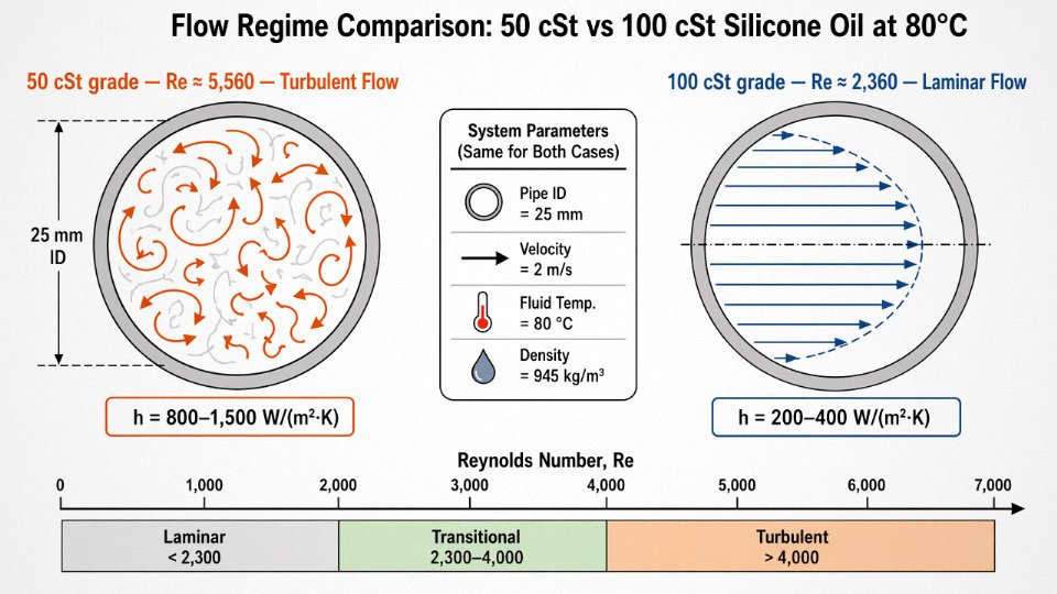
Say you have a 25 mm internal diameter pipe, targeting 2 m/s fluid velocity, with an 80°C operating bulk temperature. You’re choosing between 50 cSt and 100 cSt grades (both rated at 25°C; at 80°C these thin considerably — roughly 8–12 cSt and 18–25 cSt respectively, depending on the specific formulation).
Density for PDMS-based fluids at 80°C runs around 930–950 kg/m³. Dynamic viscosity for the 50 cSt grade at 80°C is approximately 9 cSt × 0.94 g/cm³ ≈ 8.5 mPa·s; for the 100 cSt grade, call it 20 mPa·s.
Reynolds number: Re = ρvD/μ
- 50 cSt grade: Re ≈ (945 × 2 × 0.025) / 0.0085 ≈ 5,560 — transitional, borderline turbulent
- 100 cSt grade: Re ≈ (945 × 2 × 0.025) / 0.020 ≈ 2,360 — laminar
That difference isn’t marginal. Laminar flow in a jacketed vessel means your film heat transfer coefficient might be 200–400 W/(m²·K), versus 800–1,500 W/(m²·K) in turbulent flow. To hit 10 kW duty with a laminar film you’d need substantially more surface area or a higher ΔT — both of which cost money or process flexibility you probably don’t have.
Viscosity-Temperature Behavior: Why Silicone Oils Are Forgiving (But Not Infinitely So)
Silicone oils carry a viscosity index in the 200–300 range, compared to 90–120 for a typical mineral oil. In practice, that means the viscosity-temperature curve is genuinely flat relative to what you’d see from a paraffinic heat transfer oil.
| Grade (at 25°C) | Viscosity at -20°C | Viscosity at 25°C | Viscosity at 100°C | Viscosity at 200°C |
|---|---|---|---|---|
| 20 cSt PDMS | 120–180 cSt | 20 cSt | 8–10 cSt | 5–7 cSt |
| 50 cSt PDMS | 350–500 cSt | 50 cSt | 18–24 cSt | 10–14 cSt |
| 100 cSt PDMS | 800–1,200 cSt | 100 cSt | 35–45 cSt | 18–25 cSt |
Values depend on specific formulation and molecular weight distribution — always request the supplier’s actual viscosity-temperature curve, not just the 25°C nominal.
Cold-Start: The Failure Mode Nobody Budgets For
A 100 cSt fluid sitting overnight in an unheated plant in winter can easily reach 800–1,200 cSt by the time the operator hits “start.” Most centrifugal pumps that are sized for the operating condition have nowhere near the torque margin for that. The result is either a stalled or cavitating pump, a tripped motor, or — worst case — mechanical seal damage that doesn’t show up as a failure until two weeks later.
Operational warning: if your system will see ambient temperatures below 5–10°C and you’ve specified 100 cSt or heavier, you need either electric heat tracing on the main circuit piping and pump casing, a separate low-viscosity startup charge (20 cSt grade flushed through before normal operation), or a variable-frequency drive with a controlled ramp-up that limits pump load during warmup. None of these are expensive fixes; skipping them is.
Electric heat tracing on suction piping eliminates cold-start cavitation risk for 100 cSt silicone oil systems in sub-zero ambient conditionsTrue
Maintaining fluid temperature above the point where viscosity drops to pump-safe levels (typically below 200–300 cSt) prevents the high inlet pressure drop that causes cavitation in centrifugal pumps during startup.
Viscosity Grade Selection Matrix
| System Type | Recommended Viscosity (at 25°C) | Operating Re Target | Minimum Startup Temp (unheated) |
|---|---|---|---|
| Forced-circulation jacketed vessel | 50–100 cSt | >4,000 (turbulent preferred) | 10–15°C for 50 cSt; 20–25°C for 100 cSt |
| Plate heat exchanger | 20–50 cSt | >5,000 (narrow channels, high ΔP sensitivity) | 5°C for 20 cSt |
| Tubular reactor, shell-and-tube | 50–100 cSt | >3,500 | 15°C for 100 cSt (or heat trace) |
| Immersion / static bath | 100–500 cSt | N/A (natural convection dominates) | Depends on heater wattage vs. bath volume |
| High-speed pump, long distribution loop | 20–50 cSt | Maximize; check pump curve at cold viscosity | 0°C for 20 cSt with VFD ramp |
Startup temperature thresholds assume untraced, uninsulated piping and a standard centrifugal pump without VFD. Your actual limit shifts with pipe diameter, pump head-curve shape, and ambient exposure time.
Temperature Rating Reality Check: Flash Point, Auto-Ignition, and Fluid Degradation Ceilings
The spec sheet number that gets quoted most often is the maximum service temperature — and it’s also the number most frequently misread. Engineers see “300°C continuous” and assume that means they can run their system to 295°C indefinitely without consequence. That assumption has destroyed fluid charges, wrecked vacuum pumps, and caused unplanned shutdowns on more than a few batch reactor lines. There are actually four distinct thermal thresholds that matter, and conflating them is an expensive habit.
The Four Temperatures You Need to Keep Separate
Maximum continuous service temperature is a fluid-integrity rating, not a safety cutoff. For standard PDMS grades, this sits around 200–250°C depending on the supplier and the molecular weight of the base fluid. Phenyl-modified silicones push that ceiling to roughly 280–300°C. This figure assumes a closed, well-maintained system with low dissolved-oxygen content. Run an open system or one that ingests air through a leaking expansion tank, and you’ll degrade the fluid meaningfully below that limit.
Flash point for a 50 cSt PDMS fluid typically falls in the 300–320°C range. Phenyl grades are somewhat higher, often 330°C or above. This matters for fire-risk assessments and insurance classifications, but in a properly designed closed loop, you should never approach it during normal operation. If your system’s operating temperature is anywhere near the flash point, something has gone wrong with the design — not just the fluid selection.
Auto-ignition temperature for most silicone heat transfer fluids is above 400°C. That’s a meaningful safety advantage over many synthetic hydrocarbons, which can auto-ignite in the 320–370°C range. It’s a real reason silicone fluids get specified in applications near open burners or where a catastrophic leak onto a hot surface is a credible failure mode.
Thermal degradation onset is the threshold most engineers underestimate, and it’s the one that actually governs long-term system health.
Cyclic Siloxane Formation: The Slow Failure Mode Nobody Talks About Enough
Above roughly 200°C for PDMS and around 280°C for phenyl grades, the polymer backbone begins to depolymerize. The products are volatile cyclic siloxanes — primarily D4 and D5 — that don’t stay in the fluid. They migrate up vent lines, condense in cooler sections of the piping, and eventually reach ancillary equipment. Vacuum pump oil gets contaminated within months on systems where this isn’t managed. Combustion sensors and oxygen analyzers in the same ventilated space accumulate silica deposits on their sensing elements, which causes drift and false readings. Neither failure mode announces itself dramatically; both creep up on you.
Fluid life expectancy is strongly temperature-dependent, roughly as follows:
| Fluid Type | Operating Temperature | Expected Service Life |
|---|---|---|
| PDMS 50 cSt | 150°C | >10 years |
| PDMS 50 cSt | 200°C | 3–5 years |
| PDMS 50 cSt | 230°C | 1–2 years |
| Phenyl-modified silicone | 230°C | >10 years |
| Phenyl-modified silicone | 280°C | 3–5 years |
These figures assume a closed, inerted system. Open systems or systems with chronic air ingress should shave 30–40% off those estimates.
Phenyl-modified silicone heat transfer fluids extend thermal degradation thresholds by roughly 80–100°C compared to standard PDMS grades.True
The phenyl side groups on phenyl silicone polymers increase thermal stability by reducing backbone flexibility and raising the depolymerization onset temperature, a well-established structure-property relationship in silicone chemistry confirmed across multiple supplier technical data sheets.
The 30°C Margin Rule and Why It’s Not Conservative Enough for Some Systems
A practical rule: set your system’s maximum operating temperature at least 30°C below the published maximum service temperature of your selected fluid, and program a hard high-temperature shutdown at that setpoint. That buffer absorbs sensor lag, localized hotspots near heater elements, and the occasional control excursion. In systems with electric immersion heaters — where sheath temperatures routinely run 40–60°C above the bulk fluid temperature — that 30°C margin should probably be wider.
Dissolved Oxygen: The Accelerant You Can’t See
Silicone fluids exposed to air above about 150°C oxidize at a measurable rate. The products are silicone resins and gels that gradually increase fluid viscosity, foul heat exchanger surfaces, and can eventually plug strainers. The oxidation mechanism is different from the cyclic siloxane pathway, but both are happening simultaneously in an open or poorly sealed system.
A nitrogen blanket on the expansion tank changes the picture considerably. Closed systems operating under a positive nitrogen purge typically see fluid life extended by a factor of 2–3x at the same operating temperature compared to open systems — which in practice means the difference between a 2-year fluid change interval and a 5-year one at 200°C operation. The hardware cost of a simple nitrogen blanketing setup on the expansion vessel is almost always recovered in the first avoided fluid replacement cycle.
Material Compatibility and Seal Selection: What Silicone Oil Actually Attacks in Your System
Most seal failures in silicone oil systems aren’t random. They follow a predictable pattern: someone selected the right fluid for the temperature range, got the viscosity roughly correct, then specified elastomers straight from the mineral oil system they were replacing. Six months later the pump flanges are weeping and the gaskets look like they’ve been inflated.
Elastomers: The Counterintuitive Failure Mode
The one that catches engineers most often is silicone rubber itself. It feels logical — silicone fluid, silicone gasket, same chemistry. In practice, PDMS-based fluids swell silicone elastomer (VMQ, PVMQ) by roughly 15–40%, depending on the specific elastomer formulation and service temperature. The gasket extrudes out from the flange face under bolt load and you get a slow seep that eventually becomes a drip. If you’re operating near 200°C, the swollen material also loses tensile strength fast. Don’t use silicone rubber gaskets or O-rings in silicone oil service, full stop.
PTFE and FFKM (perfluoroelastomer) are your safe defaults. Neither swells meaningfully, neither degrades at any temperature within the fluid’s service range. FFKM is expensive — budget roughly 4–8× the cost of standard FKM per O-ring — but in high-temperature loops above 250°C it’s often the only sensible choice.
Viton (FKM) is acceptable in most industrial applications up to around 200°C, with swell typically under 5% in pure PDMS service. Above 200°C, swell creeps up and the compression set behavior deteriorates; I’d treat 200°C as a hard ceiling for FKM unless you have specific immersion test data from your elastomer supplier for your exact fluid.
EPDM shows moderate swell at elevated temperatures — generally manageable below 100°C, but problematic enough above 150°C that it shouldn’t be the primary seal material in a hot loop. Natural rubber and neoprene are incompatible across essentially all service conditions and have no place in these systems.
Metals: Mostly Fine, With One Operational Trap
Carbon steel, stainless 304 and 316, aluminum, and most engineering metals are compatible with silicone oil across the full service range. Silicone fluids are notably non-corrosive to metals, which is one of their genuine operational advantages over some glycol-based and ester-based fluids.
The exception is copper and copper alloys — brass fittings, bronze pump impellers, copper brazed heat exchangers. Below about 180°C this is usually a non-issue. Above that threshold, copper acts as an oxidation catalyst for the silicone fluid, accelerating breakdown and generating acidic degradation products that then attack seals and corrode downstream components. If your system runs above 180°C and contains copper alloy components, either replace them or ensure the fluid contains appropriate antioxidant package and you’re running an aggressive fluid monitoring program. Passivation alone doesn’t fully address this; the catalytic effect is surface-area-driven and persistent.
Plastics and Coatings
Polycarbonate and ABS stress-crack on contact with silicone oil, sometimes within days under mechanical stress. This matters for sight glasses, instrument housings mounted near flange drips, and any plastic enclosure in the splash zone. HDPE, polypropylene, and PVDF are generally resistant and suitable for secondary containment, sample tubing, and drain components.
Epoxy-coated heat exchanger internals are a slower failure. Below 150°C, most industrial epoxy coatings hold up fine. Prolonged exposure above 150°C — meaning months of continuous operation — can soften the coating and cause delamination, which then contaminates the fluid and potentially plugs the exchanger. If you’re retrofitting an epoxy-lined vessel for silicone oil service above 150°C, get a coupon immersion test done first or strip and recoat with a silicone-compatible lining.
Compatibility Summary
| Material | Ambient–100°C | 100–200°C | 200–300°C |
|---|---|---|---|
| PTFE | Compatible | Compatible | Compatible |
| FFKM | Compatible | Compatible | Compatible |
| FKM (Viton) | Compatible | Compatible | Conditional |
| EPDM | Compatible | Conditional | Incompatible |
| Silicone rubber (VMQ) | Incompatible | Incompatible | Incompatible |
| Neoprene / Natural rubber | Incompatible | Incompatible | Incompatible |
| Carbon steel / SS 304/316 | Compatible | Compatible | Compatible |
| Aluminum | Compatible | Compatible | Compatible |
| Copper / brass alloys | Compatible | Conditional | Incompatible |
| HDPE / Polypropylene | Compatible | Compatible | Conditional |
| Polycarbonate / ABS | Incompatible | Incompatible | Incompatible |
| Epoxy coatings | Compatible | Conditional | Incompatible |
Conditional = usable with monitoring, design margins, or specific grade selection; verify with immersion data for your exact combination.
Pump and Valve Seal Specification
For flanged joints, specify PTFE-encapsulated spiral-wound gaskets — the spiral-wound core handles bolt load and thermal cycling, the PTFE encapsulation handles the fluid chemistry. Standard compressed fiber gaskets (especially those with rubber binders) will weep within months.
Globe valve stem packing should be PTFE, not graphite rope or braided fiber. Globe valves see repeated thermal cycles as the system ramps up and down; PTFE packing retains enough flexibility to stay leak-free through those cycles without requiring constant gland adjustment.
For centrifugal pump shafts, specify mechanical seals with carbon-ceramic faces. Carbon-ceramic handles silicone oil’s low lubricity better than competing face materials, and in my experience it’s the combination that gives the longest mean time between seal replacements in this service. Avoid rubber bellows seals with silicone elastomer components — see above.
Silicone rubber (VMQ) gaskets are incompatible with silicone oil heat transfer fluids due to excessive swell.True
PDMS-based silicone oils swell silicone elastomers by 15–40% because the polymer backbone chemistry is closely related, driving high solvent affinity and volume uptake — the opposite of the intuitive assumption that 'like material means compatible service.'
Thermal System Design Parameters: Calculating Heat Transfer Area, Flow Rate, and Fluid Inventory
The fluid selection work is done. Now the harder question: will your chosen silicone oil grade actually move enough heat through your system at the flow rates your pump can deliver? This is where a lot of designs go wrong — not because the fluid was wrong, but because the sizing assumed water-like thermal behavior.
The Cp Gap and What It Means for Mass Flow Rate
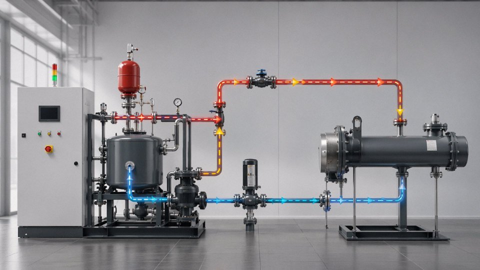
Start with the energy balance everyone knows: Q = ṁ × Cp × ΔT. Simple equation, but the Cp of PDMS silicone oil at operating temperature is roughly 1.46 kJ/(kg·K) for a 50 cSt grade at 100°C, compared to around 3.9 kJ/(kg·K) for water at the same temperature. That gap is not trivial. To carry the same thermal duty at the same temperature rise, you need approximately 2.6–2.7 times the mass flow rate compared to water. Engineers who size a silicone oil system using their water-based intuition end up undershooting flow rate and wondering why the reactor never hits setpoint.
PDMS silicone oil at 100°C has a specific heat capacity of approximately 1.46 kJ/(kg·K), roughly 2.7 times lower than water at the same temperature.True
Published thermophysical data for polydimethylsiloxane fluids consistently show Cp in the 1.4–1.55 kJ/(kg·K) range at 100°C depending on viscosity grade, versus approximately 3.9 kJ/(kg·K) for water, giving a ratio of roughly 2.6–2.7x.
Worked Sizing: 25 kW Reactor Heating Loop
Take a reactor needing 25 kW of heat input. Silicone oil enters the jacket at 180°C and leaves at 160°C — a 20°C ΔT, which is fairly typical for a moderate-duty jacketed vessel.
Required mass flow rate: ṁ = Q / (Cp × ΔT) = 25,000 W / (1,460 J/(kg·K) × 20 K) ≈ 0.856 kg/s, call it 0.85–0.90 kg/s in practice depending on the exact Cp at your mean film temperature.
PDMS 50 cSt at around 150°C has a density of roughly 900–940 kg/m³ (it drops noticeably with temperature — don’t use room-temperature density for this calculation). Using 930 kg/m³, volumetric flow rate works out to about 0.92–0.97 L/s, or roughly 55–58 L/min.
For a target velocity of 1.5 m/s — which is a reasonable starting point for forced-circulation systems, balancing erosion risk and pressure drop — the required pipe bore is approximately 28–30 mm internal diameter. A DN32 stainless line gets you there. Go down to DN25 and you’re pushing 2.3–2.5 m/s, which isn’t dangerous for silicone oil but does increase pump head requirements meaningfully, especially on a longer loop.
Compensating for Low Thermal Conductivity
Silicone oil’s thermal conductivity sits at 0.15–0.16 W/(m·K) for standard PDMS grades. That’s not disastrous, but it means laminar flow is genuinely problematic — you’re relying on conduction across a thick, slow-moving boundary layer, and the fluid’s conductivity gives you almost nothing to work with. Keep Reynolds number above 10,000 if you can. On heat exchanger selection, corrugated-plate or enhanced-surface geometries pay back their cost quickly in silicone oil service precisely because they break up the boundary layer mechanically. A smooth-tube shell-and-tube exchanger sized for water will be undersized for the same silicone oil duty, sometimes badly.
Fluid Inventory and Expansion Tank Sizing
Thermal expansion for PDMS is roughly 0.00096/°C. A system running from ambient (say 20°C) to 200°C operation sees about 17% volume expansion. Size your expansion tank dead volume at 15–20% of total fluid inventory — the upper end if you have long pipe runs or large jacketed vessels with significant hold-up. Undersizing the expansion tank is one of those problems that only shows up the first time the system reaches full operating temperature, usually on a weekend, usually with fluid on the floor.
Pipe Heat Loss: The Parasitic Load You Probably Underestimated
A 25 mm uninsulated stainless steel pipe carrying silicone oil at 200°C in a 20°C ambient will lose somewhere in the range of 120–150 W/m, depending on air movement around the pipe and surface emissivity. On a 30-meter return loop, that’s 3.6–4.5 kW of heat you’re paying to generate and then throwing away. Across 8,000 operating hours per year, that’s a meaningful energy cost, and it also means your heater is working harder than the process actually requires. Fifty millimeters of mineral wool brings that loss down to roughly 15–25 W/m. The insulation pays for itself faster than most people expect, usually within one heating season at typical energy prices. Do it at installation, not as a retrofit.
Industry-Specific Selection Criteria: Pharmaceutical, Food Processing, Semiconductor, and Chemical Reactor Applications
Selecting a viscosity grade and verifying thermal performance is only half the job. The other half is understanding that the same 100 cSt PDMS fluid that works perfectly in a plastics extrusion cooling loop would fail a GMP audit in a pharmaceutical facility, trigger an NSF non-conformance in a food plant, or contaminate a wafer batch with trace metals. Each industry has layered its own compliance requirements on top of the basic engineering criteria, and ignoring that layer costs more than just money.
Pharmaceutical Manufacturing
In jacketed reactor vessels and lyophilizer shelf systems, the fluid itself must meet FDA 21 CFR 178.3570 if there is any possibility of incidental contact with the drug substance or its container. Food-grade dimethyl silicone meeting that citation is refined to remove catalyst residues and volatile cyclic siloxanes — the technical-grade PDMS sold for industrial heat transfer is not the same product, even if the viscosity grade looks identical on a datasheet.
Technical-grade PDMS and FDA 21 CFR 178.3570-compliant dimethyl silicone can share the same nominal viscosity but differ significantly in cyclic siloxane content, catalyst residue levels, and regulatory documentation.True
Food-grade and pharmaceutical-grade silicone fluids undergo additional refining and purity testing steps; suppliers provide certificates of compliance specifically referencing the CFR citation, which technical-grade products do not carry.
GMP documentation is a practical issue here, not just a regulatory checkbox. If your system uses a non-compliant fluid and an FDA inspector asks for the fluid specification sheet during a facility audit, the absence of the 21 CFR reference creates a finding. Even in indirect-contact configurations — where the silicone oil never touches the product side — the burden of proof is on the manufacturer to demonstrate that contamination is impossible. Using a compliant fluid closes that argument before it opens.
Food and Beverage Processing
NSF H1 registration covers lubricants and heat transfer fluids where incidental food contact is possible. In chocolate tempering systems, viscosity grade matters more than in most other food applications because the tempering jacket runs at relatively tight temperature bands (27–32°C seed zone, roughly), and a fluid that’s too viscous at startup creates uneven shell temperatures. Most tempering machine manufacturers specify 20–50 cSt grades, and in practice 20 cSt tends to win out in smaller batch systems where pump sizing is conservative.
Brewing fermentation jackets are less demanding thermally but spend long periods at near-ambient temperatures, which means any fluid with marginal low-temperature flow behavior will stratify or slug-pump during glycol switchover events. Low-volatility, odor-free grades are non-negotiable in open cooking or fermentation environments — a faint silicone odor drifting into a fermenter room is enough to trigger a quality hold, regardless of actual contamination risk.
Semiconductor and Electronics Manufacturing
Ultra-pure silicone fluids used in immersion cooling test chambers and wafer process equipment operate at 5–20 cSt and are specified to particle counts typically below 100 particles larger than 0.5 µm per mL. Metal ion limits — sodium, potassium, iron — run in the sub-ppb range because even trace contamination can affect photoresist adhesion or gate oxide integrity downstream. Standard industrial PDMS fails these specifications badly. The supply chain for semiconductor-grade silicone fluid is short; there are only a handful of qualified suppliers globally, and lead times of 8–14 weeks are not unusual. Procurement managers who treat this as a standard industrial fluid will get caught short during a tool qualification cycle.
Compatibility with photoresist chemistry is worth verifying specifically rather than assuming. Some photoresist strippers and developers will cause minor swelling in elastomeric seals lubricated or wetted by silicone oil — not the fluid itself causing the problem, but the combined chemical environment.
Specialty Chemical and Polymerization Reactors
High-temperature jacket service at 250–300°C in polymerization reactors almost always points toward phenyl-modified silicone fluids rather than straight PDMS, because phenyl content shifts the oxidative stability ceiling upward and reduces thermal expansion behavior at process temperature. The less-discussed problem is monomer absorption. Styrene and several acrylate monomers have measurable solubility in PDMS at elevated temperatures; if a seal fails and monomer enters the jacket-side fluid, viscosity will drift and the fluid inventory may need replacement well ahead of its normal service interval.
Quarterly viscosity checks on large-inventory systems (say, anything over 200 L of fluid) are reasonable practice. Annual acid number measurement and particle count testing catch oxidative degradation and seal wear respectively — the two failure modes that actually terminate fluid life in this service. If the acid number climbs above roughly 0.1 mg KOH/g, start planning a replacement, not hoping it stabilizes.
Solar Thermal and Concentrated Solar Power
Phenyl silicone fluids have found a niche in parabolic trough collectors running at 250–300°C as an alternative to synthetic biphenyl-diphenyl eutectic fluids. The eutectic blends are effective heat transfer media but carry significant toxicity concerns, require specialized disposal, and are regulated as hazardous materials in several jurisdictions. High-purity phenyl silicone carries a 20–35% higher first-cost premium (depending on system inventory size and current biphenyl pricing), but disposal at end-of-life is straightforward by comparison, and there is no acute exposure risk during maintenance.
The honest caveat: phenyl silicone’s thermal conductivity and specific heat capacity are slightly lower than the eutectic fluid it replaces, so heat exchanger area requirements may increase modestly. That’s a capital cost tradeoff to run through the system economics before committing, not an afterthought.
Fluid Maintenance, Monitoring, and End-of-Life Management for Silicone Heat Transfer Systems
Silicone oil is genuinely durable compared to most synthetic heat transfer fluids, but “durable” does not mean indestructible, and in practice the maintenance programs at most facilities are where silicone systems fail — not in the initial selection. A fluid that cost $15–30/liter and was correctly specified gets degraded by a slow air leak at the expansion tank, or contaminated by a failed pump seal, or left in service two years past its useful life because nobody set up a monitoring program at commissioning. The cost of that neglect is usually not a dramatic failure; it’s a slow drift in heat transfer performance, increased pump energy draw, and eventually fouled heat exchanger surfaces that require chemical cleaning or tube replacement.
Building a Monitoring Schedule That Actually Gets Followed
The practical starting point is deciding which parameters matter and what triggers action. For most industrial silicone heat transfer systems, a quarterly sample pulled from the return line (not the drain cock, which gives you settled sediment, not representative fluid) covers the critical bases.
Kinematic viscosity is the primary indicator. A shift greater than roughly 15% from the new-fluid baseline — either direction — warrants investigation before the next scheduled sample. Viscosity climbing usually means oxidative polymerization or cross-linking at hotspots; viscosity dropping can indicate thermal cracking or contamination with a lighter fluid. Either condition degrades your Reynolds number assumptions and heat transfer coefficient calculations from the original system design.
Acid number matters most in food-grade or pharmaceutical circuits. Above 0.1 mg KOH/g, the fluid is generating acidic degradation products that can attack soft metals and accelerate elastomer degradation. In a standard industrial system you might tolerate slightly more, but that threshold is a reasonable trigger for attention regardless.
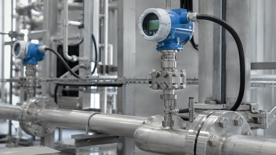
Particulate contamination above NAS Class 8 is the threshold for precision systems — semiconductor thermal management, reactor jacket circuits with tight clearance control valves. For general industrial use, Class 10 is a more realistic action limit. Color change is a cheap leading indicator: any darkening toward amber or brown, or the appearance of haze, signals oxidation or moisture ingress long before viscosity numbers move significantly. Dissolved water above roughly 200 ppm in a closed system means something is wrong — a heat exchanger leak, condensation in an improperly sealed expansion tank, or a compromised nitrogen blanket. Water in hot silicone oil accelerates hydrolysis and will eventually generate silica particulates that foul narrow passages.
Filtration: Sizing for Cold-Start Reality
A 10–25 µm nominal full-flow filter on the pump discharge handles normal particulate load, but the bypass valve sizing is where engineers make mistakes. A 100 cSt fluid at 25°C may be 8–12× more viscous than it is at operating temperature; without an adequately sized bypass, cold-start pressure drop across the filter can cavitate the pump or trip the differential pressure alarm before the system is even warm. Size the bypass to open at roughly 1.5–2× the design operating differential pressure. Pharmaceutical and semiconductor applications typically add a 5 µm absolute secondary filter downstream of the primary — the pressure drop penalty is acceptable when the alternative is silica fines reaching a sensitive heat exchanger.
Nitrogen Blanketing: Simple, Frequently Skipped
A nitrogen connection at the expansion tank maintaining 0.02–0.05 bar positive pressure is one of the highest-return-on-investment modifications you can make to an existing system. The mechanism is straightforward: thermal cycling drives the fluid level up and down, and without positive pressure, that cycling pumps air — and moisture — into the headspace every cycle. At 200°C continuous operation, oxidative degradation roughly follows an Arrhenius relationship; field experience and supplier data consistently suggest that eliminating oxygen exposure can extend fluid service life by a factor of 2–3×. The hardware cost is a regulator, a check valve, and some tubing. The nitrogen consumption is negligible. Yet a surprising number of plants running silicone heat transfer systems above 180°C are still operating open expansion tanks.
Nitrogen blanketing at 0.02–0.05 bar positive pressure can approximately double or triple silicone oil service life at elevated temperatures by preventing oxidative degradation.True
Silicone oil oxidation at temperatures above 150–200°C follows temperature-accelerated kinetics; oxygen exclusion removes the primary degradation pathway. Fluid suppliers including Shin-Etsu and Clearco document significantly extended service intervals for blanketed systems in their technical bulletins.
Fluid Change-Out: The Flush Step Most Facilities Skip
Draining degraded silicone oil and filling with fresh fluid without an intermediate flush is a common mistake. Heat exchanger passages, dead legs, and pump casings retain a film of degraded fluid — oxidized oligomers, silica fines, acidic byproducts — that contaminates the fresh charge within the first few operating hours. The correct procedure is a hot flush: drain the bulk fluid, charge with a low-viscosity PDMS flush fluid (5–10 cSt grade), circulate at operating temperature for 4–8 hours, drain completely, then charge the new working fluid. It adds cost, but not nearly as much as discovering six months later that your “new” fluid already has an acid number above specification and color that matches what you drained out.
Disposal: Less Complicated Than Most Engineers Expect, With One Caveat
Fresh or lightly used silicone oil is not classified as hazardous waste in most jurisdictions — it has low acute toxicity, low aquatic toxicity, and is not listed under most regulatory frameworks in the US, EU, or China. Used fluid from normal industrial service is typically handled as non-hazardous industrial waste and can often be reclaimed by the original fluid supplier or a licensed recycler.
The caveat is fluid that has seen sustained high-temperature operation above roughly 250°C. At those conditions, cyclic siloxanes (D4, D5, D6) can accumulate in the fluid, and the degraded solid fraction is essentially amorphous silica — neither of which changes the regulatory classification in most regions, but both of which affect disposal method. Incineration at a licensed facility is usually the preferred route for heavily degraded fluid. The practical advice: before disposal, call your fluid supplier’s technical service line and describe the operating history. They can advise whether reclamation is feasible or whether you’re looking at incineration, and they’ll usually have the right waste handler contacts. Don’t assume the maintenance contractor hauling the drum knows the answer.
Total Cost of Ownership Analysis: Comparing Silicone Oil Against Alternative Heat Transfer Fluids Over a 10-Year Horizon
The sticker price on silicone oil — typically $8–$18/liter depending on viscosity grade, purity tier, and order volume — stops a lot of procurement conversations before they start. That’s the wrong place to stop. For any system running above 150°C with a design life of 10 years or longer, the initial fluid fill cost is usually the smallest line item in the total economic picture. What dominates are replacement cycles, maintenance labor, energy penalties from fouling, downtime, and disposal.
The 10-Year Cost Structure for a 500-Liter Jacketed Reactor
Take a representative 500-liter jacketed glass-lined reactor running a process that cycles between 20°C and 200°C. That’s a common configuration in fine chemical and API manufacturing, and it puts real stress on the fluid because of the repeated thermal cycling and moderate oxygen exposure at the expansion tank.
| Cost Category | PDMS 50 cSt Silicone Oil | Mineral Oil-Based Fluid | Synthetic Hydrocarbon (Therminol 66 type) |
|---|---|---|---|
| Initial fill cost (500 L) | $4,000–$9,000 | $500–$1,200 | $2,500–$5,000 |
| Expected fluid life at 200°C | 8–12 years | 2–4 years | 5–8 years |
| Fluid replacements over 10 years | 0–1 | 2–4 | 1–2 |
| Fluid replacement labor + flush (per event) | $1,500–$3,000 | $1,500–$3,000 | $1,500–$3,000 |
| Annual heat exchanger cleaning | Every 5–7 years | Every 12–18 months | Every 2–3 years |
| Estimated downtime per cleaning (hours) | 8–12 | 16–24 | 12–16 |
| Fluid disposal cost (per replacement) | $100–$300 | $800–$2,500 | $600–$2,000 |
Figures depend on local labor rates, fluid degradation rate (heavily influenced by peak temperature excursions and oxygen ingress), and whether the cleaning can be scheduled or is forced by performance loss.
The Fouling Energy Penalty Is Not Abstract
This one gets underestimated almost every time. A silicone oil system operating at 180°C with clean surfaces carries a fouling resistance (Rf) roughly in the range of 0.0001 m²·K/W. A mineral oil system after two to three years of operation — especially if the fluid has been running above its recommended ceiling and has started laying down oxidative deposits — can reach Rf values around 0.0004–0.0005 m²·K/W on the jacket wall. That difference translates, in practice, to an 8–12% increase in heater energy consumption to maintain the same process-side temperature, all else equal.
A fouled mineral oil heat transfer system operating at 180°C typically requires 8–12% more heater energy than a clean silicone oil system at the same temperatureTrue
The energy penalty follows directly from degraded overall heat transfer coefficient (U-value) caused by higher fouling resistance on the jacket wall. With Rf increasing from ~0.0001 to ~0.0005 m²·K/W, U drops materially, requiring higher fluid temperature (and therefore more heater output) to maintain the same process-side heat flux.
At an industrial electricity or gas rate of $0.06–$0.12/kWh and a reactor running 5,000–6,000 hours per year, that 8–12% penalty on a 20–50 kW heater adds up to roughly $600–$4,300 per year in wasted energy. It’s not a rounding error over a decade.
Disposal and Compliance — A Real and Growing Cost
Mineral oil-based heat transfer fluids, once contaminated with oxidative breakdown products or process cross-contamination, are classified as hazardous waste in most European and North American jurisdictions above certain thresholds. Disposal fees run $0.50–$2.00/liter, sometimes higher for halogenated or heavy-metal-contaminated streams. On a 500-liter system replaced twice in 10 years, that’s $500–$2,000 in disposal alone, before accounting for the documentation burden, manifesting requirements, and contractor scheduling.
Silicone oil — specifically unfilled, unadditized PDMS that hasn’t picked up process contamination — often qualifies as non-hazardous in the same jurisdictions, reducing this cost category substantially. That said, if the fluid has been contaminated by process leakage, all bets are off and you’re managing the contaminating substance, not the silicone.
Insurance and Liability: The Number Nobody Puts in a Spreadsheet
In pharmaceutical and food processing applications, the financial case shifts dramatically because of product recall exposure. A heat transfer fluid leak through a failed jacket fitting or a pinhole in a heat exchanger wall can contaminate a batch. With mineral oil or synthetic hydrocarbon fluid, that contamination is a regulatory event — potentially a full product recall, a facility audit, and in the worst case, a consent decree. A single recall in a mid-size oral solid dosage facility can run into the millions.
Food-grade or pharmaceutical-compliant silicone oil (NSF HT1 registered, or equivalent) doesn’t eliminate that risk entirely, but it dramatically reduces the regulatory consequence of accidental contact. That’s not a theoretical benefit — any procurement manager who has sat through a recall cost analysis conversation understands this immediately.
Where the Crossover Actually Falls
Run the full 10-year net present value across all cost categories — fluid purchase, replacements, labor, energy penalty, downtime, disposal, and a risk-weighted compliance cost — and for most continuous process systems operating above 150°C, silicone oil reaches cost parity with mineral oil somewhere in the year 3–5 window. After that crossover it’s increasingly advantageous, and the advantage widens at higher temperatures because mineral oil degradation accelerates nonlinearly above about 180°C.
Against synthetic hydrocarbon fluids like Therminol 66, the gap is narrower. The crossover typically comes later, around year 5–7, depending heavily on actual operating temperature and whether the application carries any compliance premium. In purely thermal-economic terms, the case for silicone over synthetic hydrocarbons is strongest at the temperature extremes (above 250°C or below -40°C) and in regulated industries where the compliance value tips the balance.
The premium price per liter is the price of admission. Everything after that tends to favor silicone.
Frequently Asked Questions About Silicone Oil Selection for Heat Transfer
Can I use general-purpose silicone oil from an industrial supplier instead of a dedicated heat transfer fluid grade?
No — and this mistake shows up more often than it should. General-purpose silicone oils sold for mold release, lubrication, or cosmetic formulation are not formulated with thermal stabilizers or antioxidant packages. Run them above roughly 150°C in a circulating system and you’ll see viscosity creep upward within weeks, followed by varnish deposits on heater surfaces and eventually flow restriction in narrow passages. The base polymer is technically the same PDMS, but what’s missing is everything that makes it survive thermal cycling over thousands of hours.
Always ask for a published maximum service temperature on the technical data sheet, and confirm there’s an explicit thermal stability test result — not just a boiling point or flash point. If the supplier can’t provide that, treat the product as unsuitable for heat transfer duty regardless of price.
General-purpose PDMS silicone oils are interchangeable with dedicated heat transfer fluid grades if the viscosity matches.False
General-purpose grades lack thermal stabilizer and antioxidant packages present in dedicated heat transfer fluids, leading to accelerated degradation, viscosity increase, and deposit formation at sustained temperatures above 150°C.
What viscosity grade works best for a small laboratory recirculating bath running between -20°C and +150°C?
The standard recommendation here is 20–50 cSt at 25°C. At the cold end, lower viscosity keeps your pump from cavitating or stalling on startup — this matters a lot if your bath controller ramps from ambient down to -20°C quickly. At the warm end, that viscosity range still gives you an acceptable heat transfer coefficient in the small-bore tubing typical of lab baths. Several manufacturers offer specifically formulated wide-range bath fluids in this class, sometimes labeled “thermal bath fluid” rather than a straight viscosity grade, and they tend to handle repeated thermal cycling better than a plain 20 cSt PDMS.
Avoid the temptation to go lower than 10 cSt for a lab bath. Thin fluids are harder to contain, evaporate more at the upper end, and don’t offer enough thermal mass for stable temperature control in bench-scale equipment.
How do I know when silicone oil has reached end of service life?
Silicone fluids don’t usually fail dramatically. There’s no color change like you get with a severely oxidized mineral oil, no obvious smell, no foam. What you get instead is a slow drift in viscosity — once that shift exceeds roughly 15–20% from the original specification, flow distribution through your system is no longer matching your design assumptions, and heat transfer efficiency starts dropping in ways that are easy to misattribute to other causes.
Track viscosity, visual appearance (haze or any gel strands are a serious warning), and acid number on a quarterly sampling schedule for critical systems. Annual sampling is the absolute minimum for any continuous process. Don’t rely on appearance alone.
Is silicone oil compatible with 316L stainless steel heat exchangers?
Yes, fully. 316L is compatible across the entire silicone oil service temperature range with no corrosion, no catalytic breakdown of the fluid, and no surface preparation required. In practice, most well-maintained silicone oil systems run in all-stainless or carbon steel circuits without issue for many years. The problems come from elastomers and coatings, not the metalwork.
Can I top up a silicone heat transfer system with a different fluid if I run low?
Never mix silicone oil with mineral oil, glycol blends, or synthetic hydrocarbon fluids. The result is either phase separation or gel formation, both of which will block strainers and damage pump seals faster than almost any other single maintenance error. If you need to top up, use the identical product from the same manufacturer — even switching between two different silicone oil brands of the same nominal viscosity carries some risk if the additive packages are incompatible. When changing grades entirely, do a full drain and hot-flush before refilling.
What are the environmental and safety implications of a silicone oil spill?
PDMS-based fluids have very low acute toxicity — oral LD50 values for most grades run above 50 g/kg in rat studies, and they’re not classified as aquatic hazards under most regulatory frameworks. The real hazard is physical: silicone oil on a concrete floor is essentially invisible and almost frictionless. Serious slip-and-fall incidents happen in plants that don’t treat silicone spills with the same urgency as a hydraulic oil leak. Cleanup requires silica-based or mineral clay absorbents — paper towels and standard oil-dry products work poorly because the fluid’s low surface tension lets it spread and penetrate aggressively. Seal the area immediately.
Does altitude affect silicone oil performance?
For most systems operating below 250°C, altitude effects are negligible. Reduced atmospheric pressure does lower effective boiling point, but silicone oil flash points typically sit above 300°C, well clear of normal operating windows. The only time to run vapor pressure calculations for altitude is if you’re designing a system that intentionally operates near the fluid’s upper thermal limit — a high-temperature reactor cooling loop at a facility above roughly 2,500 meters elevation, for instance. Otherwise, this is not a variable that warrants engineering time in routine selection.