Composites delaminate. Rubber compounds lose filler dispersion after six months on the shelf. Glass-fiber-reinforced parts crack at the fiber–matrix interface under load that the design said they could handle. In every one of these cases, the root cause traces back to the same interface chemistry failure: the inorganic surface and the organic matrix never bonded properly in the first place. The downstream costs are not abstract — scrapped batches, warranty returns, line stoppages while engineers chase a processing variable that was actually a formulation variable.
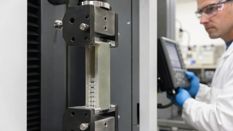
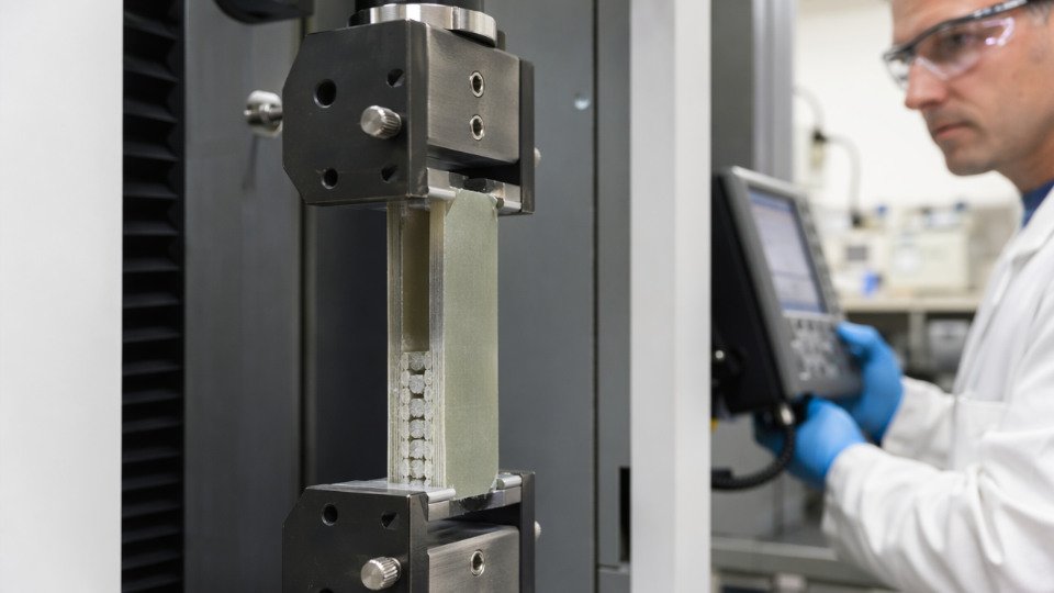
Silane coupling agent performance is determined by how completely the silane hydrolyzes and condenses onto an inorganic surface, then co-reacts with the organic matrix. At correct loading — typically 0.5–3.0 phr in rubber systems, with 1.0–1.5 phr covering most adhesion-critical applications — and under controlled pH and moisture conditions, aminosilane-treated glass fiber composites consistently show 40–80% higher tensile strength than untreated controls.
What makes this chemistry worth understanding at a mechanistic level is that the silane does not simply act as a glue layer. It creates a gradient interphase — a zone that is neither purely inorganic nor purely organic — and the mechanical, chemical, and thermal properties of that interphase are tunable in ways that most procurement and processing decisions never exploit. The gap between minimum acceptable performance and optimized performance is wide, and most plants are operating somewhere in the middle without knowing it.
Molecular Structure Variables That Control Coupling Efficiency
Every silane coupling agent is essentially three functional zones bonded to a silicon center: the hydrolyzable alkoxy groups that anchor to inorganic surfaces, an organofunctional group that reacts with the polymer matrix, and a spacer chain connecting the two. Changing any one of these zones shifts the performance envelope. Knowing which lever to pull — and why — separates a competent formulation from one that is just copying a competitor’s trade name.
Alkoxy Leaving Group Identity
The three most common hydrolyzable groups are methoxy, ethoxy, and acetoxy. Methoxysilanes hydrolyze roughly 3–5× faster than their ethoxy counterparts under equivalent pH and temperature conditions; hydrolysis half-lives for trimethoxysilane groups in neutral water at 25 °C typically fall in the 5–15 minute window, while triethoxysilanes run 15–30 minutes (both figures shift sharply below pH 4 or above pH 9). That speed difference matters in waterborne sizing formulations and aqueous coupling baths: methoxy systems can gel or deposit oligomeric siloxane before the glass fiber or silica surface is adequately wetted, which shortens your usable pot life to under an hour in warm-season plant conditions. Ethoxysilanes give more working time at the cost of releasing ethanol, which carries its own ventilation requirements but is toxicologically preferable to methanol in confined mixing areas. Acetoxysilanes are fast-hydrolyzing and leave acetic acid as a byproduct — corrosive to metal substrates and incompatible with moisture-sensitive matrices like certain polyurethanes.
Organofunctional Group and Matrix Compatibility
This is where most selection errors happen. The organofunctional group must be chemically reactive — or at minimum compatible — with the specific polymer matrix, not just the broad resin family.
| Functional Group | Target Matrix Chemistry | Reaction Mechanism |
|---|---|---|
| Amino (primary/secondary) | Epoxy, polyurethane, polyamide | Ring-opening, H-bonding, salt formation |
| Epoxy (glycidoxy) | Epoxy, acrylic, polysulfide | Epoxide ring-opening |
| Vinyl | Unsaturated polyester, PE/PP with peroxide | Radical co-polymerization |
| Methacryloxy | Acrylic, unsaturated polyester | Radical co-polymerization |
| Mercapto | Epoxy, natural rubber, polysulfide | Thiol-ene, oxidative coupling |
| Isocyanato | Polyurethane, hydroxyl-functional resins | Urethane bond formation |
| Sulfido (bis-silane, TESPT) | Silica-filled rubber | Sulfur-radical coupling with elastomer |
Applying an aminosilane to a purely radical-cure polyester system, for instance, produces no covalent bond at the organic interface — you get adsorption rather than coupling, and tensile strength improvement drops from the 40–80% range seen with correct selection to essentially noise-level gains.
Spacer Chain Length and Flexibility
The methylene bridge between silicon and the organofunctional group is not decorative. Short-chain silanes (C1–C3) pack tightly at the surface, which benefits thermal stability — the Si–O–surface bond is less subject to hydrolytic cleavage when the chain cannot flex into configurations that draw in water. Longer chains (C6–C11) improve surface wettability during the deposition step and reduce steric crowding when functional group density is high, but they increase molecular weight, which feeds directly into volatility concerns at processing temperature.
Mono-, Di-, and Trifunctional Architectures
Trifunctional silanes build a denser siloxane network at the interphase. That density drives moisture durability — critical in automotive glass laminates or outdoor composite panels — but the rigid crosslinked layer can become a crack initiation site in flexing applications. Monofunctional silanes create essentially a monomolecular tether; the interphase stays compliant but has less redundancy against hydrolytic attack over time. Difunctional systems split the difference and are often the working compromise in rubber-to-metal bonding where both flex fatigue and humidity aging matter.
TESPT as a Sulfido Silane Benchmark
Bis-triethoxysilylpropyl tetrasulfide (TESPT) is the reference point for silica-filled tire tread compounds. Its sulfur rank distribution — typically a mixture of di-, tri-, and tetrasulfide bridges averaging around S3.5–S4 — controls both scorch safety and coupling yield. Higher average sulfur rank means more sulfur available for rubber network formation but also earlier onset of premature crosslinking during high-temperature mixing. Processors running internal mixers above 150 °C often switch to the disulfide analog (TESPD) to buy scorch safety, accepting a modest reduction in reinforcement efficiency. Loading in rubber compounds typically runs 0.5–3.0 phr, with the 1.0–1.5 phr band delivering the best balance of coupling yield and compound viscosity; going above 2.5 phr without adjusting sulfur donor levels risks over-crosslinking at the silica surface rather than in the bulk rubber.
Methoxysilanes hydrolyze faster than ethoxysilanes under equivalent conditionsTrue
Methoxy groups are better leaving groups due to lower steric bulk and higher electrophilicity at silicon; this is well-established in organosilicon chemistry and consistent with measured hydrolysis kinetics in the peer-reviewed literature.
Molecular Weight, Volatility, and Mixing Temperature
Lower-molecular-weight silanes diffuse to the filler surface faster during mixing — an advantage in short-cycle internal mixer operations. The penalty is vapor pressure. A silane with a boiling point near or below your mixing temperature (often 140–160 °C for rubber, higher for thermoplastic composites) will partially volatilize before it reacts, meaning your nominal 1.5 phr loading may deliver effective coupling closer to 0.8–1.0 phr. This is one reason lab-scale optimizations at 100 °C sometimes fail to translate to plant-scale performance — the silane budget calculated on paper does not survive the thermal history of a production Banbury.
Hydrolysis and Condensation Kinetics: Rate-Limiting Steps in Real Processing Conditions
Getting the chemistry right at the substrate surface depends almost entirely on controlling two sequential reactions: hydrolysis of the alkoxy groups to silanols, then condensation of those silanols onto substrate hydroxyl sites. Both steps have rate constants that shift dramatically with pH, temperature, water activity, and silane concentration — and in a running production process, you rarely have the luxury of optimizing all four simultaneously.
pH Dependence: A Double-Edged Catalyst
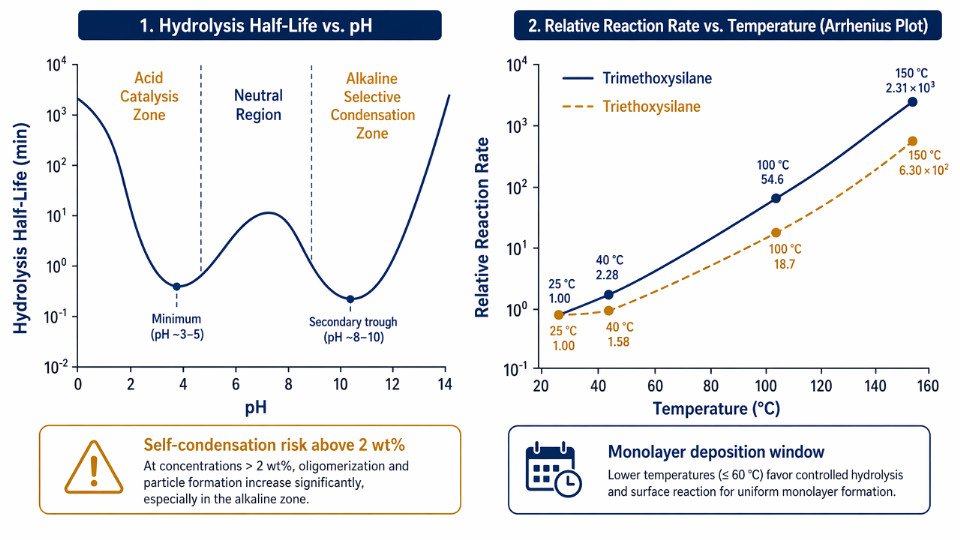
Acid catalysis in the pH 3–5 range accelerates silanol formation by protonating the alkoxy leaving group, cutting the hydrolysis half-life of trimethoxysilane groups from roughly 20–30 minutes at neutral pH down to 5–10 minutes under the same temperature conditions. That sounds like a straightforward win, but the same proton activity that speeds hydrolysis also promotes silanol–silanol self-condensation. You end up with oligomeric polysiloxane species in solution before the molecule ever reaches the glass fiber or silica surface. The result is a thick, poorly anchored multilayer deposit rather than a controlled monolayer — and in glass-fiber-reinforced composites, that soft interlayer actually reduces tensile strength instead of improving it.
Alkaline conditions (pH 8–10) shift the equilibrium toward slower hydrolysis but more selective surface-directed condensation. The substrate silanol density is higher under alkaline treatment, and the longer residence time in hydrolyzed monomer form gives molecules a better statistical chance of finding a surface site before reacting with a neighbor. For silica-filled rubber systems where you are compounding rather than fiber sizing, slightly alkaline mixing conditions often produce better filler dispersion and lower compound viscosity — both of which trace back to this kinetic selectivity.
Temperature and Activation Energy
Arrhenius data for trimethoxysilane hydrolysis puts the activation energy in the 50–70 kJ/mol range, depending on substituent and solvent. Practically, that means a 10 °C rise roughly doubles the reaction rate — so a fiber sizing bath running at 40 °C versus 25 °C is not a minor operational variable. For ambient-cure systems such as silane primers applied to concrete or metal substrates at room temperature, expect 2–6 hours for full hydrolysis and initial condensation under typical plant humidity conditions (40–60% RH). Oven-cure schedules at 100–120 °C collapse that window to 10–20 minutes, but if the oven ramps too fast before surface moisture equilibrates, you drive off water before condensation is complete.
Raising cure temperature always improves silane coupling agent bond strengthFalse
Excessive temperature or rapid ramp rates can dehydrate the surface before condensation completes, reducing interfacial bond density and lowering composite mechanical performance.
Water Concentration and Solvent System Design
Dilute aqueous-alcohol solutions — typically 0.5–2 wt% silane in 80–95% ethanol or methanol/water blends — are the standard for glass fiber manufacturing sizing baths. The alcohol slows condensation kinetics enough to maintain monomer stability in the bath for practical cycle times of 1–4 hours, depending on silane chemistry and bath temperature. Non-aqueous sizing systems (anhydrous carriers with controlled micro-dosing of water) are used in specialty applications where bath life must extend beyond a single shift, but they require tighter process controls and are sensitive to ambient humidity ingress.
Self-condensation versus substrate condensation is ultimately a competition governed by local silane concentration and substrate hydroxyl density. At silane concentrations above roughly 2 wt%, the intermolecular collision frequency dominates, and oligomers form in solution. Below 0.5 wt%, hydrolysis is slow and bath productivity suffers.
Moisture in Fillers: A Frequently Underestimated Variable
Residual moisture in precipitated silica or mineral fillers above approximately 0.3 wt% will hydrolyze and partially condense the silane during mixing — before it reaches the filler surface at a useful concentration. The silane is consumed reacting with free water in the matrix rather than bonding to hydroxyl groups on silica particles. Effective coupling agent concentration available for interfacial bonding drops, compound Mooney viscosity climbs, and bound rubber content falls. Pre-drying fillers to below 0.2 wt% moisture before silane addition is a process discipline that consistently pays back in compound consistency.
Tracking Reaction Progress Analytically
Solution-state ²⁹Si NMR remains the most direct method for quantifying the distribution of Q species — T1 (one siloxane bond formed), T2, and T3 — giving a real-time snapshot of how far condensation has progressed in a sizing bath or reaction mixture. TGA weight loss profiles between 100–300 °C correlate with surface-bound silane loading on treated fillers, though separating physisorbed versus chemisorbed fractions requires careful baseline correction. ToF-SIMS depth profiling of treated fiber or film surfaces resolves the actual thickness and silicon concentration gradient of the deposited layer — useful for diagnosing whether you have a monolayer or a condensed oligomer deposit.
Performance in Rubber and Elastomer Compounds: Mechanical and Dynamic Properties
Coupling agent chemistry only earns its keep when it translates into measurable compound behavior on the mixing room floor and, ultimately, in service. For rubber formulators, that translation runs through three distinct performance axes: static mechanical properties, dynamic viscoelastic response, and processing behavior during internal mixing.
Sulfido Silanes in Precipitated-Silica Tire Treads
TESPT (bis[3-(triethoxysilyl)propyl] tetrasulfide) and TESPD (the disulfide analog) became the industrial standard for passenger tire tread compounds precisely because precipitated silica — unlike carbon black — forms a persistent filler network through hydrogen bonding between silanol groups. That network is the Payne effect: strain-dependent modulus drop that costs rolling resistance and wet grip simultaneously, pulling in opposite directions from a formulation standpoint.
At practical loadings of 6.4–8.0 phr TESPT in an 80 phr silica compound, Payne effect reduction of 50–70% is routinely measured between 0.1% and 60% strain amplitude, though the actual figure depends on silica surface area (typically 160–200 m² g⁻¹ for tire-grade precipitated silica), mixing temperature profile, and silanization time. The mechanism is straightforward: the triethoxysilyl end reacts with surface silanols, blocking the H-bond network; the sulfide chain then participates in vulcanization, forming a covalently bonded organic–inorganic interphase.
The dynamic consequence matters commercially. Tan δ at 60°C — the rolling resistance proxy — typically falls 15–30% relative to an uncoupled silica compound, while tan δ at 0°C (wet grip proxy) can improve 5–15%. These numbers are not independent; they depend on cure system selection, silica loading, and whether TESPD or TESPT is used. TESPD’s shorter polysulfide chain reduces premature sulfur donation during mixing but typically delivers slightly lower silanization efficiency at equivalent loading.
Mooney Viscosity and Processability
Mooney viscosity reduction of 20–35% at equivalent silica loading is the processing dividend of effective silanization. Unreacted silica surface creates enormous hydrodynamic reinforcement through filler–filler networking; good coupling suppresses that and makes the compound flow through transfer lines, extruders, and calendering nips without the energy spikes that signal poor dispersion. Mixer energy input during the silanization dump — measured in kWh/kg — is an indirect efficiency indicator worth tracking. A compound that silanizes fully at 155°C in 4–5 minutes will show a characteristic viscosity plateau; premature dumping produces a compound that continues reacting in the bin, causing inconsistent downstream behavior.
TESPT at 6.4–8.0 phr in an 80 phr precipitated-silica SBR compound reduces the Payne effect by 50–70% compared to uncoupled controlsTrue
This range is consistent with peer-reviewed silica compounding literature and is reproducible under controlled mixing protocols; the spread reflects differences in silica surface area, mixer design, and temperature profile rather than formulation uncertainty.
Mercaptosilanes, Scorch Safety, and Crosslink Density
Mercaptopropyltriethoxysilane (MPTS) and blocked mercaptan silanes (NXT-type chemistry) deliver faster silanization kinetics because the thiol group reacts more readily with rubber chains than polysulfide does. Crosslink density increases are measurable — equilibrium swelling and stress-relaxation data typically show 10–25% higher crosslink density in MPTS-coupled silica compounds relative to TESPT at equivalent loading — but the price is scorch sensitivity. Free mercaptans become reactive above 140°C, making dump temperature control non-negotiable. A mixing stage that drifts to 165°C instead of 155°C can initiate premature crosslinking before the compound reaches the mill, resulting in scrap that looks perfectly mixed but fails cure rheometry.
Static Mechanical and Fatigue Properties Across Polymer Types
In NR compounds, effective silica coupling with sulfido silanes raises tensile strength 20–40% and elongation at break drops modestly (typically 5–15%) as the interphase stiffens the network. Tear strength, which depends heavily on interphase crack blunting, improves more variably — 15–35% — and is highly sensitive to silane loading optimization; under-coupled compounds fail cohesively at the silica agglomerate boundary, leaving visible white pull-outs in the tear surface.
SBR and E-SBR systems show similar trends but require tighter scorch management because of their lower thermal stability. EPDM compounds using silica for thermal insulation or white sidewall applications benefit from aminosilane or vinylsilane coupling where sulfur cure systems are absent, though mechanical improvement is more modest — 10–20% tensile gain — because the coupling chemistry must rely on physical entanglement or peroxide co-crosslinking rather than polysulfide integration.
Heat build-up under cyclic deformation is the fatigue durability metric that often separates adequate from excellent coupling. A poorly coupled interphase debonds progressively under strain cycling, generating internal friction and heat. Compounds with complete silanization typically show 10–20°C lower core temperatures in the DIN drum fatigue test at equivalent load, and crack initiation in flex fatigue is delayed substantially — sometimes doubling the cycles to failure — because the interphase remains intact under the stress concentrations that would otherwise nucleate voids at the filler surface.
Performance in Thermoset and Thermoplastic Composite Matrices
Fiber-reinforced plastics and mineral-filled engineering thermoplastics present a fundamentally different performance challenge than rubber compounding. The cure chemistry is irreversible, the fiber-matrix interphase is locked in during processing, and delamination or interfacial debonding under load or moisture does not recover. Getting the silane chemistry right at the sizing stage is not a correctable downstream decision.
Matching Silane Functionality to Matrix Cure Chemistry
The most commercially consequential example of functional group mismatch is using vinylsilane on glass fiber destined for an epoxy matrix. Vinylsilane participates in free-radical polymerization — it is purpose-built for unsaturated polyester and vinyl ester systems. In an epoxy cure, no free radicals are generated; the crosslinking proceeds through amine or anhydride ring-opening of the epoxide. A vinylsilane-treated fiber sitting inside a curing epoxy resin forms no primary covalent bond at the interphase. The result is interfacial adhesion governed largely by van der Waals forces and mechanical interlocking, not covalent grafting.
Aminosilane (typically 3-aminopropyltriethoxysilane or its trimethoxy equivalent) reacts directly with epoxide groups via nucleophilic addition. The primary amine opens the epoxide ring under the same thermal conditions used to cure the laminate, building a continuous covalent network from glass surface through coupling agent into the resin. Tensile strength improvements versus untreated glass in aminosilane-epoxy systems run 40–80%, depending on fiber volume fraction, weave architecture, and the completeness of silane hydrolysis and condensation prior to lamination. Incomplete condensation — caused by insufficient drying of the sized fiber before prepreg manufacture — leaves residual silanol groups that later hydrolyze out of the interphase under service moisture.
MPS in Unsaturated Polyester and Acrylic Systems
Methacryloxypropyltrimethoxysilane (MPS) earns its dominant position in unsaturated polyester (UP) and acrylic matrices because its methacrylate terminus co-polymerizes directly with styrene and unsaturated ester double bonds during free-radical cure. This is true interphase copolymerization, not physisorption. The practical outcome is interlaminar shear strength (ILSS) gains of 30–60% over bare or poorly sized glass, with the range depending on styrene content in the resin, cure initiator type, and fiber surface cleanliness. At low MPS loadings on the fiber, physisorption begins to dominate — you lose the co-polymerization mechanism and ILSS drops back toward untreated values. Over-application creates a thick, under-crosslinked silane layer that becomes a cohesive weak zone under interlaminar shear loading. The practical optimum on fiber surface coverage is narrow enough that sizing bath concentration and fiber dwell time need process control, not just a target number.
Epoxy Silane in Mineral-Filled Engineering Thermoplastics
In nylon 6, nylon 66, and PBT filled with calcium carbonate, wollastonite, or talc, glycidoxypropyltrimethoxysilane (GPS) provides the coupling mechanism between mineral surface hydroxyls and polar matrix chains. Charpy notched impact strength gains of 15–40% relative to untreated filler are typical, and — critically for under-hood and structural housings — HDT (heat deflection temperature) retention after 1,000 hours of humid aging improves measurably. The mechanism is not purely covalent with nylon; GPS reacts with carboxyl and amine end groups of the polyamide. End-group concentration in the specific nylon grade therefore affects coupling efficiency, a variable that commodity filler suppliers rarely account for in their silane recommendations.
Epoxy silane coupling agents improve moisture-aged impact retention in mineral-filled nylon compared to untreated filler.True
Peer-reviewed compounding studies and ISO 179 Charpy testing after humid aging consistently show 15–40% impact strength retention improvements attributable to hydrolytically stable Si-O-mineral bonds limiting interfacial debonding during water uptake.
Carbon Fiber: Where Silane Chemistry Hits Its Limits
Oxidized carbon fiber surfaces carry carboxyl, hydroxyl, and carbonyl groups — chemically reactive sites that silane alkoxy groups can, in principle, bond to via Si-O-C linkages. In practice, three complications erode performance. First, the fiber’s surface energy varies with oxidation level, which is process-dependent and not always consistent lot to lot. Second, commercial carbon fiber arrives with a proprietary sizing already applied; applying silane over that sizing treats the sizing surface, not the fiber. Stripping the sizing before silane treatment recovers fiber reactivity but risks damaging the surface and adds process cost. Third, Si-O-C bonds are measurably less hydrolytically stable than Si-O-Si bonds formed on silica or glass, meaning moisture durability in carbon fiber-reinforced polymer (CFRP) applications using silane alone is limited without complementary interphase engineering.
Moisture Durability Protocols and What They Actually Test
ASTM D2247 (continuous 100% relative humidity exposure) and boiling water immersion tests stress the interphase through repeated swelling and hydrolytic attack. Autoclave cycling — used in aerospace qualification — combines temperature and pressure to accelerate moisture ingress. The governing failure mode in all three is hydrolytic reversal of siloxane bonds at the fiber-resin interphase. A silane system with good dry-state ILSS but poor retention after 500 hours in boiling water has an interphase that performs during fabrication quality checks and fails in service. ILSS retention below 70% after boiling water immersion is a practical rejection threshold many aerospace and marine procurement specifications use, though the exact threshold depends on application load case and safety factor.
Hybrid Silane Sizings for Commingled Fabric Preforms
Commingled fabrics — where thermoplastic fiber (typically PA or PPS) is woven together with glass reinforcement — demand a sizing that bonds to glass during thermoplastic processing without degrading during the high-temperature consolidation step. Neither aminosilane nor GPS alone solves this cleanly. Co-deposited or sequentially applied hybrid silane systems, where an epoxy-functional silane provides glass adhesion and an amino-functional silane provides reactivity toward the thermoplastic matrix end groups, have demonstrated ILSS improvements of 20–45% over single-functional sizings in commingled PA6/glass laminates. The processing constraint is that consolidation temperature for PA6 is above 220°C; the silane interphase must survive that thermal exposure without degrading its bond to the fiber surface. Silane selection for commingled preforms therefore involves thermal stability screening — typically TGA to 300°C in air — before any mechanical testing begins.
Surface Coverage, Deposition Uniformity, and Characterization Methods
Knowing that silane coupling agent was added to the process is not the same as knowing it worked. Batch records confirm dosage; they tell you nothing about what actually happened on the substrate surface. The gap between nominal treatment and verified surface chemistry is where a significant fraction of composite failures, filler dispersion problems, and adhesion inconsistencies originate.
Monolayer Coverage: What You’re Actually Targeting
A theoretical close-packed monolayer of trimethoxysilane on silica requires roughly 2–4 molecules/nm², which translates to approximately 1–3 mg of silane per m² of substrate surface area. The exact figure depends on the molecular footprint of the specific organosilane and the hydroxyl site density of the substrate — fumed silica with 4–6 silanols/nm² behaves differently from precipitated silica or glass fiber with variable surface conditioning history. Staying within this monolayer-equivalent regime matters because multilayer deposition produces a thick, poorly crosslinked polysiloxane layer that behaves as a weak boundary layer under mechanical stress rather than a load-transferring interphase. More silane is not better silane.
XPS: Ground Truth for Surface Chemistry
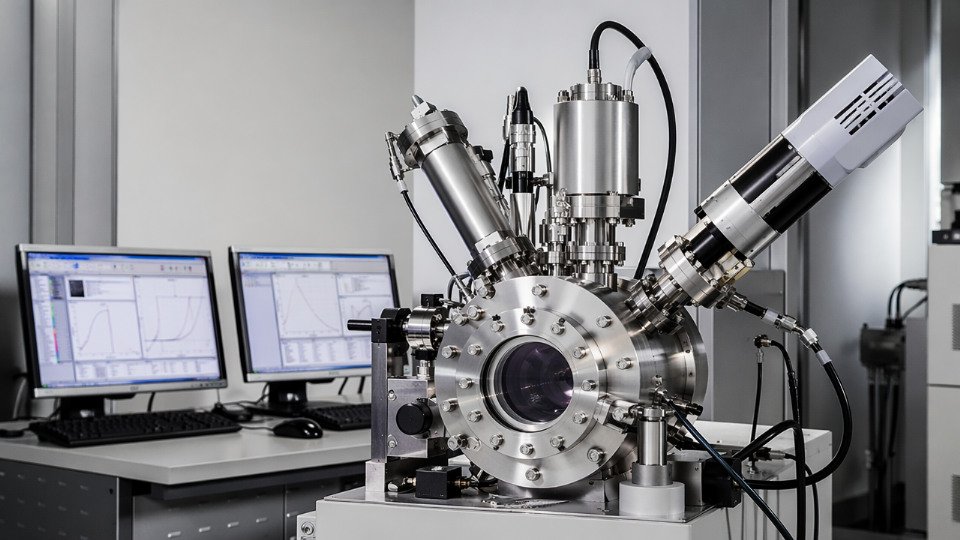
X-ray photoelectron spectroscopy gives you elemental composition and oxidation state within the top 5–10 nm of a treated surface — precisely where the coupling chemistry must occur. For aminosilane-treated glass fiber, you confirm successful grafting through the N 1s signal at approximately 399–400 eV (free amine) versus a shift to 401–402 eV when the amine is protonated or involved in hydrogen bonding. For sulfur-functional silanes used in silica-rubber systems, S 2p binding energy distinguishes unreacted thiol from disulfide or polysulfide species, which matters because the sulfur oxidation state directly affects crosslink density in the vulcanizate. Si 2p signals allow you to ratio substrate silicon against deposited organosilane silicon, giving a quantitative coverage estimate. The technique is slow and expensive — not a production QC tool — but it is the appropriate reference method when qualifying a new substrate, a new silane supplier, or troubleshooting a field failure.
DRIFT Spectroscopy: Confirming Reaction Completion
Diffuse reflectance infrared Fourier transform spectroscopy is faster and more accessible than XPS, and it answers a different but equally critical question: has the silane reacted with the surface, or is it just sitting there? The Si-O-Si band near 1050–1100 cm⁻¹ and the Si-O-metal stretch around 900–960 cm⁻¹ confirm condensation has occurred. Residual Si-OH stretching around 3700 cm⁻¹ and the persistence of methoxy C-H bands near 2840 cm⁻¹ indicate incomplete hydrolysis or condensation — physisorbed silane that will wash off or migrate under processing heat. In a practical filler-treatment operation, DRIFT spectra taken before and after a thermal cure step quickly reveal whether your oven temperature and dwell time are sufficient.
DRIFT spectroscopy can distinguish chemisorbed silane from physisorbed silane on silica surfacesTrue
Chemisorbed silane shows characteristic Si-O-metal and Si-O-Si condensation bands in the 900–1100 cm⁻¹ region; physisorbed silane retains intact methoxy groups and free silanol bands that disappear only after hydrolysis and condensation are complete.
TGA: Quantifying Organic Loading on Treated Fillers
Thermogravimetric analysis gives you total organic content on the filler surface by measuring mass loss between roughly 300–800°C after subtracting adsorbed water losses below 200°C. For a silica with a BET surface area of 150–200 m²/g, a monolayer-equivalent treatment with a C8 alkylsilane might produce 2–5 wt% organic loading. Significantly higher values — say above 8–10 wt% on the same substrate — suggest multilayer buildup, which correlates with poorer filler dispersion and inconsistent compound viscosity batch to batch. TGA data only become meaningful when normalized to surface area; comparing raw weight-percent numbers across fillers with different surface areas misleads formulation decisions.
Contact Angle: Fast, Actionable, Imperfect
Water contact angle measurement on flat substrates or pressed filler discs is the closest thing the industry has to a rapid surface treatment check. Bare silica or untreated glass sits below 10°, highly hydrophilic. A successful aminosilane treatment typically shifts contact angle to 60–80°; alkylsilane treatments push it above 90°, rendering the surface hydrophobic. The test takes minutes. Its limitation is that it integrates over a relatively large surface area and cannot distinguish a uniform thin monolayer from patchy multilayer coverage that averages to the same angle. Use it as a go/no-go gate, not as a coverage quantification method.
Operational warning: Contact angle alone passing specification has been observed in production situations where DRIFT or TGA later revealed inadequate condensation — the silane was present but not properly bonded. A contact angle check clears physisorbed silane just as readily as chemisorbed silane.
Industrial QC: Carbon Analysis and Batch Consistency
For high-volume filler treatment operations — silica compounding, glass fiber sizing, mineral-filled thermoplastics — the practical QC stack is combustion carbon analysis (CHNS), combined with BET surface area measurement and lot-to-lot extraction gravimetry. Carbon loading normalized to surface area (mg C/m²) is the most reproducible metric for batch consistency. Control charting this value against compound performance metrics closes the loop between surface chemistry quality and end-use mechanical properties. Acceptable tolerance bands depend on the sensitivity of the downstream compound to coverage variation; filled rubber compounds for dynamic applications typically require tighter surface treatment control than static structural composites.
| Method | Measures | Typical Use Case | Limitation |
|---|---|---|---|
| XPS | Elemental composition, oxidation state, top 5–10 nm | Qualification, failure analysis | Slow, expensive, lab-only |
| DRIFT | Reaction completion, bond type | Process development, incoming filler QC | Quantification requires calibration |
| TGA | Total organic loading | Routine batch QC on treated fillers | Must normalize to BET surface area |
| Contact angle | Wettability, hydrophilic/hydrophobic shift | Fast go/no-go on flat substrates | Cannot confirm bond quality |
| CHNS combustion | Carbon content | High-volume production QC | No bond-type information |
Selecting the right characterization tool depends on what question you are actually asking. Qualifying a new silane grade or diagnosing a delamination failure justifies XPS and DRIFT. Controlling daily filler treatment production justifies CHNS plus contact angle. Running both without a defined accept/reject criterion wastes resources; running neither means the quality of your interface chemistry is entirely assumed.
Aging, Durability, and Failure Mechanisms of the Silane Interphase
Long-term performance is where silane coupling agent selection gets decided in practice. A compound that tests well at day zero can degrade to near-untreated baseline within months of field exposure if the interphase was not designed for the actual service environment. Understanding the mechanisms — not just the symptoms — lets engineers build in durability rather than chase it retrospectively.
Hydrolytic Reversal of Si–O–Substrate Bonds
The Si–O–Si and Si–O–metal bonds at the substrate surface are thermodynamically metastable in the presence of liquid water. The same hydrolysis equilibrium that enables silane deposition can run in reverse: water displaces the siloxane linkage, regenerating surface silanols and effectively delaminating the interphase. In humid air at 50–80% RH the driving force is modest and bond reversal is slow; in continuous liquid-water immersion, particularly at elevated temperatures, bond cleavage can become the dominant degradation pathway within weeks.
Multilayer silane deposition — often seen as a defect — provides an unintended benefit here. A condensed siloxane network 3–5 nm thick acts as a diffusion barrier that slows water ingress to the primary bond plane. The tradeoff is that thicker deposits introduce cohesive failure risk within the silane layer itself. Optimal coverage for hydrolytic durability sits in a narrow window: dense enough to retard diffusion, thin enough to maintain cohesive integrity. That window depends heavily on substrate hydroxyl density and deposition pH control during treatment.
Hydrolytic bond reversal at the silane–substrate interface is thermodynamically favorable in liquid water at ambient temperatureTrue
The Si–O–metal and Si–O–Si bonds formed during condensation are susceptible to nucleophilic attack by water; this is the same equilibrium exploited during the hydrolysis step of silane deposition, simply running in reverse under aqueous service conditions.
Thermal Degradation Pathways
Above roughly 200–230°C, alkylene spacer groups in silane molecules become vulnerable to oxidative chain scission. This matters in high-temperature thermoplastic compounding — glass-fiber-reinforced polyamide or polyphthalamide processed above 280°C can partially destroy the organic functionality of aminosilane or epoxysilane treatments applied to the fiber before compounding. The result is reduced fiber–matrix adhesion relative to what the fiber sizing specification suggests.
Polysulfide silanes used in silica-reinforced rubber present a separate thermal problem. The sulfur rank distribution shifts during high-temperature mixing: tetrasulfide bonds redistribute toward lower sulfur ranks, altering the reactive sulfur pool available for coupling. If mixing temperature drifts above 160–170°C — which can happen in poorly controlled dump conditions — premature pre-reaction reduces the amount of silane available to couple at the silica surface, and re-agglomeration of silica aggregates becomes measurable through Payne effect increases in the final compound.
Cyclic Mechanical Fatigue at the Interphase
Fatigue loading does not simply weaken the bulk composite; it preferentially initiates debonding cracks at surface sites with incomplete silane coverage. In glass-bead-filled polymers, stress whitening under cyclic strain is a direct visual indicator of this process — void formation around partially bonded particles scatters light before bulk fracture occurs. Interphase toughness, not just bond strength, determines crack arrest: a compliant interphase layer with some capacity to deform plastically outperforms a brittle, high-modulus one under fatigue conditions, particularly at stress concentrations near fiber ends or particle equators.
UV and Weathering Degradation
In exterior composites, UV exposure attacks the organic coupling chemistry directly. Aminosilane-promoted epoxy interfaces are particularly vulnerable: the amine group sensitizes the adjacent epoxy network to photolytic oxidation, accelerating chain scission near the interphase. UV stabilizer selection must account for this — hindered amine light stabilizers (HALS) can interact unfavorably with aminosilane chemistry, and the stabilizer package should be validated at the interphase level, not just in the bulk resin.
Accelerated Aging Test Design and Field Correlation
The 85°C/85% RH protocol (per IPC-TM-650 and similar automotive specifications) remains the industry workhorse for combined thermal-hygroscopic stress. Correlation to field service life requires a defined acceleration factor, which ranges from roughly 8× to 40× depending on the actual service environment and activation energy of the dominant degradation mechanism. A protocol without a validated correlation factor produces ranking data — useful for comparative selection — but not life prediction. Automotive underhood applications typically add cyclic thermal shock (−40°C to 150°C) to the hygroscopic soak to capture interphase fatigue from differential thermal expansion.
Self-Healing Interphase Concepts
At the research stage, bis-silane systems incorporating dynamic covalent bonds — disulfide or boronate ester linkages in the organic spacer — can partially re-form interphase connections after mechanical debonding under moderate thermal stimulus. Nanoencapsulated silane reservoirs embedded in the matrix offer a second approach: capsule rupture during crack propagation releases fresh silane that migrates to the debonded surface. Neither approach is commercially established in volume production, but both represent credible engineering solutions to the fundamental problem that debonding is currently irreversible once initiated.
Industrial Application Engineering: Dosage Optimization, Mixing Protocols, and Cost-Performance Trade-offs
Calculating Theoretical Dosage from Filler Surface Area
Start with the filler’s BET surface area — not the supplier’s nominal figure, but a measured value on the actual production lot, since surface area on precipitated silica can range 150–220 m²/g and shifts with moisture and storage time. The calculation runs: BET surface area (m²/g) × target surface coverage (typically 0.3–0.5 mg silane per m²) ÷ silane molecular weight (g/mol) = theoretical loading in mmol per gram of filler. Convert that to phr for rubber by multiplying by filler phr and silane molecular weight. For a 50-phr precipitated silica at 180 m²/g using TESPT (molecular weight ~539 g/mol), a 0.4 mg/m² target yields roughly 2.0–2.5 phr — consistent with the 0.5–3.0 phr practical range, but now tied to your specific filler rather than guessed from a data sheet.
Underdosing leaves uncoated silica surface available to absorb water and plasticizer, raising Payne effect and dynamic heat build-up. Overdosing wastes material at USD 6–12/kg for common sulfido silanes, and excess silane plasticizes the compound, reducing modulus and hardness below spec. Neither failure is obvious in a short Mooney viscosity check — you see it in dynamic mechanical analysis or after 100,000 fatigue cycles.
Pre-treatment Versus In-Situ Silanization
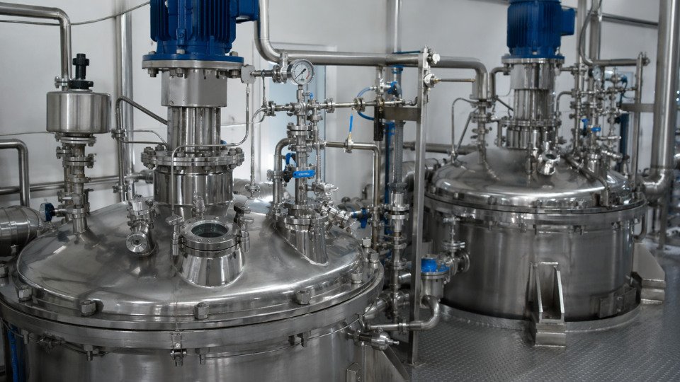
Pre-treating filler in a ribbon blender or fluidized-bed reactor before it enters the mixer gives more controlled reaction: temperature, residence time, and alcohol vapor removal can each be managed independently. Reaction completeness with spray-on pre-treatment at 120–140°C and 20–40 minutes residence time is generally higher than in-situ addition, and the treated filler can be inventoried. The downside is capital — a dedicated pre-treatment vessel, VOC extraction hood, and solvent recovery unit — plus the need to requalify the filler’s surface chemistry if it sits in storage beyond a few weeks.
In-situ addition to an internal mixer is lower capital and the dominant practice in tire and industrial rubber plants. The constraint is that silanization must complete during the first mixing stage before curatives enter. This is why the two-stage mixing protocol matters.
Two-Stage Mixing and Temperature Discipline for Sulfido Silanes
First stage: all polymer, silica, TESPT or TESPD, and processing aids go in together. The dump temperature target is 150–155°C, held for sufficient time to drive the condensation reaction and release ethanol. Drop below 145°C and silanization is incomplete; push above 160°C and polysulfidic silanes begin releasing active sulfur, initiating premature crosslinking — scorch marks in the batch, wasted material, and a fouled rotor to clean.
Second stage: cool the batch below 110°C before adding zinc oxide, stearic acid, accelerators, and sulfur. Mercaptosilanes are particularly sensitive here — their thiol group reacts directly with zinc and accelerators at elevated temperature, consuming both and leaving inconsistent cure kinetics across production runs.
Alcohol Emission and Ventilation Requirements
Each mole of triethoxysilane releases up to three moles of ethanol on hydrolysis. In a 300-liter internal mixer running a 50-phr silica compound, a single batch can generate 50–150 g of ethanol vapor depending on silane type and loading. Methoxy-functional silanes release methanol, which carries higher toxicity and stricter exposure limits. Enclosed mixers require a continuous exhaust draw with flowrates sized to keep vapor concentration well below 25% of the lower explosive limit — typically 500–1,200 m³/h extraction for a production-scale mixer. Condensation recovery units upstream of the scrubber reclaim solvent and reduce VOC compliance burden; payback on that capital runs 2–5 years depending on silane consumption volume and local solvent disposal costs.
Methoxy-functional silanes release methanol during hydrolysis and condensation, requiring stricter occupational exposure controls than ethoxy-functional analogues.True
Methanol's TLV-TWA (ACGIH) is 200 ppm, lower than ethanol's 1000 ppm, and it is classified as a skin-absorption hazard. This difference directly affects ventilation design specifications and personal protective equipment requirements in production environments.
Economic Justification and Formulation Interactions
Silane cost runs USD 3–15/kg depending on functional group complexity, with aminosilanes and specialty blocked mercaptosilanes at the high end. The economic case rarely rests on silane cost alone. A 10–20% filler loading increase enabled by effective silanization reduces compound cost per unit volume; a 15–30% cut in reject rate from delamination failures is measurable in the first production quarter. Extended service life — the hardest to quantify upfront but often the largest value driver in automotive or industrial sealing applications — requires field data.
One formulation interaction that routinely causes problems: calcium carbonate coated with stearic acid. The fatty acid monolayer occupies the same hydroxyl sites silane targets. Adding silane to pre-coated calcium carbonate without surface area adjustment gives apparent underdosing because effective reactive surface area is already partially blocked. Uncoated calcium carbonate or grades with partial coating require separate BET characterization and dosage recalculation. Similarly, zinc oxide added too early in a mercaptosilane compound forms zinc mercaptide complexes that alter both coupling efficiency and cure rate — staging ZnO to the second mix stage solves this without any formulation change.
| Interaction | Effect if Ignored | Correction |
|---|---|---|
| Fatty acid-coated filler + silane | Incomplete surface coverage, low adhesion | Measure effective uncoated BET; recalculate dosage |
| ZnO + mercaptosilane, first-stage mix | Premature complex formation, erratic cure | Stage ZnO to second mix below 110°C |
| Excess silane + accelerator | Silane acts as plasticizer; viscosity drops | Titrate loading via BET calculation, not rule-of-thumb |
| Methoxy silane in enclosed mixer, no VOC extraction | Methanol accumulation, explosion and health risk | Size extraction to <25% LEL; add condensation recovery |
Emerging Performance Frontiers: Nano-Enabled Systems, Green Chemistry, and Digital Optimization
The next decade will not simply refine how silane coupling agents are applied — it will restructure the underlying assumptions about surface geometry, feedstock origin, regulatory headroom, and process knowledge.
Silane Coupling Agents on Nanofillers: When Curvature Changes the Rules
Conventional silane deposition theory assumes a relatively flat substrate. Once primary particle radius drops below roughly 20 nm — typical of fumed silica aggregates, graphene oxide platelets, and cellulose nanocrystals — that assumption breaks. High surface curvature forces silane headgroups into a fan-like arrangement rather than a planar monolayer, reducing lateral Si–O–Si condensation between neighboring molecules and lowering effective crosslink density at the interphase. The practical result: optimal silane loading per unit surface area on a 10–15 nm particle can run 20–40% higher than on a 300 nm conventional filler at equivalent mass fraction, depending on BET surface area and the silane’s organic chain length. Nanoclay presents a different complication — interlayer gallery spacing of 1–2 nm may physically exclude bulkier organofunctional groups before hydrolysis even completes. Formulators who simply transfer a proven silane dose from a conventional-filler compound into a nanofilled system routinely see underperformance and attribute it to dispersion when the real bottleneck is insufficient interfacial bond density.
Bio-Based Silane Alternatives: Functional Parity Without Petrochemical Feedstocks
Amino acid-derived silanes (using lysine or cysteine backbones as the organic tether) and fatty-acid-derived variants have demonstrated tensile retention in glass-fiber composites within 5–15% of conventional 3-aminopropyltriethoxysilane benchmarks in laboratory screening studies. Lignin-alcohol-derived silanes are earlier-stage but show promise in cellulosic composite systems where feedstock chemistry compatibility reduces phase incompatibility penalties. The trade-off is currently cost — bio-derived intermediates carry a 30–80% raw material premium over petrochemical equivalents at current production scale — and less predictable lot-to-lot consistency until synthetic routes mature. For procurement managers, the calculus shifts when customer specifications or regional regulations impose supply-chain sustainability requirements that price in the alternative cost of reformulation later.
Bio-based silane coupling agents can achieve coupling efficiency comparable to conventional aminosilanes in glass-fiber-reinforced systemsTrue
Peer-reviewed laboratory studies have demonstrated tensile and interlaminar shear strength retention within approximately 5–15% of petrochemical aminosilane benchmarks for amino acid-derived silane variants, though commercial-scale consistency and cost parity have not yet been established.
Waterborne and Solvent-Free Formulations Under Regulatory Pressure
EU Directive 2010/75/EU and parallel US EPA VOC rules are tightening permissible alcohol emissions from silane treatment lines. Reactive oligomeric siloxane systems — pre-hydrolyzed, partially condensed silane oligomers dispersed in water — sidestep the ethanol and methanol byproduct problem by eliminating the hydrolysis step at the point of application. Performance is broadly comparable to solvent-borne equivalents when oligomer molecular weight and degree of pre-condensation are controlled tightly. The operational warning: shelf stability of waterborne siloxane dispersions is pH-sensitive, typically requiring pH 4–5 to prevent premature gelation, and bath life in spray or dip application is measured in hours rather than days without refrigeration.
Machine Learning and High-Throughput Silane Screening
Combinatorial silane libraries — 50 to 200 candidate structures screened by automated interlaminar shear strength (ILSS), Payne effect, or peel adhesion assays — combined with DoE-guided regression models are compressing silane selection cycles from months to weeks in well-resourced R&D environments. The practical ceiling is data quality: ML models trained on a narrow substrate or cure chemistry set generalize poorly, and mislabeled experimental batches propagate noise that degrades model confidence intervals faster than adding more data points corrects them.
Plasma and Photochemical Grafting for Electronics and Biomedical Applications
Atmospheric-pressure plasma and UV-initiated silane grafting deposit functional layers in the 0.5–5 nm range with process control that conventional wet chemistry cannot approach. In flexible electronics, where adhesion failure between substrate and encapsulant at a 20 nm interphase directly determines device lifetime under flex fatigue, this precision is not optional. Cycle time is short — typically 5–30 seconds of plasma exposure — but throughput and capital cost remain barriers for anything outside high-value components.
Digital Twin Modeling of Interphase Formation
Finite element analysis coupled to reaction-diffusion kinetics can now predict local silane conversion as a function of real processing variables: mold temperature gradients, atmospheric humidity at the mixer inlet, and shear history in a twin-screw extruder. A model calibrated on a specific silane-filler-matrix system can flag zones of incomplete condensation before a part is ever demolded. The current limitation is calibration burden — each new silane chemistry requires its own kinetic parameter set, and gathering those parameters from designed experiments adds 4–8 weeks to a development program. As parameter databases expand and instrument integration improves, this gap will close.
Frequently Asked Questions About Silane Coupling Agent Performance
These questions surface repeatedly from compounders, process engineers, and procurement teams. Each answer draws on what actually goes wrong on the plant floor, not just textbook chemistry.
Can one universal silane work across all substrates and resins?
No, and this is one of the costliest misconceptions in the industry. Functional group chemistry must be matched at both ends simultaneously — the silane’s organofunctional group must react with the matrix (amine silanes for epoxy systems, methacryloxy silanes for unsaturated polyesters, sulfido silanes for sulfur-cured rubbers), and the substrate must present sufficient surface hydroxyl density for the alkoxy groups to anchor. A vinylsilane applied to an epoxy matrix will deliver almost no covalent coupling; in some cases the silane layer acts as a release agent, and you end up with lower interfacial strength than untreated filler. The match between silane chemistry and substrate surface chemistry is non-negotiable before you even think about dosage.
How do I know if my silane has actually reacted rather than just physisorbed on the filler surface?
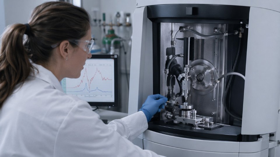
DRIFT-IR (Diffuse Reflectance Infrared Fourier Transform spectroscopy) is the practical first check. You are looking for the disappearance of isolated silanol O–H stretching bands around 3740 cm⁻¹ and the growth of broad Si–O–Si network bands in the 1000–1100 cm⁻¹ region. Physisorbed silane will retain narrow silanol character; chemisorbed silane will not. Pair that with thermogravimetric analysis: calculate the theoretical organic mass for one monolayer coverage based on your filler’s BET surface area and the silane’s molecular footprint, then compare against measured TGA weight loss in the 200–600°C window. If measured loading far exceeds the theoretical monolayer, you have a multilayer deposit, some of which is likely weakly bound. Neither test alone is conclusive; together they give a reasonable production QC picture.
What is the shelf life of a prepared silane solution?
Dilute aqueous silane solutions — typically below 2 wt% — should be used within 4–8 hours of preparation. Hydrolysis starts immediately on mixing, and condensation follows; by 8–12 hours in open or poorly controlled conditions, oligomeric siloxane particles begin forming and the solution loses effectiveness for substrate treatment. Neat silanes sealed under dry nitrogen in original manufacturer containers have shelf lives of roughly 12–24 months when stored at 5–25°C away from moisture. Once a container has been opened and resealed without nitrogen blanketing, that window shortens considerably — budget for 6–9 months and test accordingly.
Does increasing silane loading always improve mechanical performance?
Beyond monolayer coverage, excess silane reduces rather than improves mechanical performance in filled polymer systems.True
Multilayer silane deposits are cohesively weak because outer layers are not covalently bound to the substrate; under mechanical stress these layers fail internally, reducing impact strength and increasing water absorption relative to optimally treated systems. Peer-reviewed composite data consistently confirm this inflection point at approximately 1–2 monolayer equivalents.
The optimum is typically 1–2 monolayer equivalents of coverage. Running a dosage sweep in your specific system and measuring both tensile strength and impact strength is worth the bench time — impact often peaks at a lower loading than tensile, and over-treating a high-surface-area filler like precipitated silica can noticeably increase compound water uptake.
Are trialkoxysilanes safe to handle in industrial settings?
They are moderate irritants, but methoxy variants carry an additional hazard: methanol is released during hydrolysis, and methanol vapor accumulates quickly in enclosed mixing or treatment areas. Ethoxy variants are generally preferred where process conditions allow, since the byproduct ethanol is significantly less toxic. For any trialkoxysilane, local exhaust ventilation at the point of addition, nitrile gloves, and chemical splash goggles are the minimum PPE per standard SDS requirements. Review your specific silane’s SDS before scaling up from lab to production — flash points and exposure limits vary meaningfully across product families.
How does ambient humidity affect silane performance during filler treatment?
Above roughly 60% RH in an open treatment system, self-condensation of the silane solution accelerates visibly. Silane molecules react with each other rather than with the substrate surface, forming oligomers that deposit unevenly and bond poorly. The consequence is patchy coverage — you may pass average TGA loading checks while having localized areas of thick, weak multilayer deposit alongside bare substrate. Enclosed treatment systems or humidity-controlled application areas (target 40–55% RH) are the practical fix. Some operations humidify slightly below 40% RH to slow solution aging when batch processing takes longer than two hours.
What is the difference between a silane coupling agent and a silane crosslinker?
A coupling agent is bifunctional in a bridging sense: one end anchors to the inorganic phase (filler, fiber, or glass), and the other end reacts into the organic polymer matrix. The function depends on two distinct phases being present. A silane crosslinker — vinyltrimethoxysilane (VTMS) used in moisture-cure crosslinked polyethylene is the canonical example — reacts with the polymer backbone (via peroxide-initiated grafting) and then uses its trialkoxysilyl groups to form Si–O–Si bridges between polymer chains when exposed to moisture. There is no mineral interface involved. Confusing the two leads to serious formulation errors: specifying a crosslinker where a coupling agent is needed leaves your filler essentially untreated.