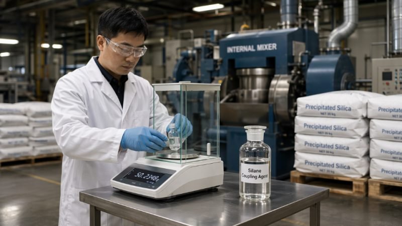
Silane coupling agent dosage is one of those process variables that looks deceptively simple on a technical data sheet but punishes guesswork hard on the production floor. Underload the silane and you leave filler surfaces uncoated, which means poor matrix adhesion, elevated compound viscosity, and — in rubber or composite applications — mechanical properties that fail qualification testing. Overload it and you pay twice: once for the excess silane that forms wasteful polycondensate multilayers instead of useful bonds, and again in the form of plasticization, blooming, or processing instability that generates scrap and reruns. Getting the number right the first time is a matter of applying surface chemistry systematically, not adjusting by feel.
Optimal silane coupling agent dosage is determined by matching silane quantity to the available reactive surface area of the filler, typically 0.5–2.0 wt% on total filler for general filled systems and 6–12 wt% on filler for precipitated silica in rubber compounds. The correct starting point is the filler’s BET surface area and silanol density, combined with the silane’s molecular footprint — then confirmed through small-scale coupling efficiency tests before locking in a production formulation.
What makes this genuinely difficult in practice is that “dosage” is not one number — it shifts with filler lot-to-lot surface area variation, mixing temperature, moisture content, and whether you are treating in-situ or pre-treating offline. The same silane at the same nominal loading can behave like a completely different material depending on those upstream variables. Understanding the surface chemistry logic behind the calculation, rather than just copying a formulation from a supplier data sheet, is what separates a robust process from one that drifts every time a new filler shipment arrives.
Substrate Surface Chemistry as the Primary Input Variable for Dosage Calculation
Every silane dosage question starts in the wrong place when engineers reach for a rule-of-thumb percentage before measuring what the filler actually demands. The substrate defines the theoretical silane requirement. Everything else — silane type, process conditions, end-use performance targets — modifies that baseline.
BET Surface Area Is the Foundation, Not a Secondary Specification
Total reactive surface area, measured by BET nitrogen adsorption and expressed in m²/g, directly sets the moles of silane required to deposit a functional monolayer. The governing calculation is straightforward:
Grams of silane = (BET surface area [m²/g] × filler mass [g] × molecular footprint [m²/molecule]) ÷ Avogadro’s number
For a typical aminosilane with a molecular footprint of roughly 0.40–0.55 nm² on silica, treating 100 g of fumed silica at 200 m²/g works out to approximately 1.1–1.5 g of silane at theoretical monolayer coverage. Run that same calculation on a precipitated silica at 160 m²/g versus a ground calcium carbonate at 6 m²/g and you immediately see why a single weight-percentage target applied across both fillers is operationally wrong — not slightly off, but wrong by an order of magnitude.
Hydroxyl Density Varies Sharply Across Filler Types
BET area tells you how much surface exists. Surface hydroxyl density tells you how much of it can react. Amorphous precipitated and fumed silica carry 4–8 silanol groups per nm², which is why these fillers are the natural pairing for alkoxysilane coupling agents. Crystalline quartz sits at roughly 5 OH/nm² but with lower accessibility because of its ordered surface structure. Calcite and talc present very low reactive OH density — talc in particular has a largely inert basal plane — so conventional trialkoxysilanes provide minimal covalent bonding on these substrates. Forcing a standard silane dosage onto talc-filled polypropylene without adjusting chemistry or accepting that you are relying on physical adsorption rather than covalent coupling is a source of chronic adhesion failures that compound-level troubleshooting rarely diagnoses correctly.
Carbon black sits in a separate category entirely. Its surface chemistry is dominated by edge carbons and oxidized functional groups, not silanols, so alkoxysilane coverage is weak. Sulfur-functional silanes used in carbon black-containing rubber are operating through a different interaction mechanism, and dosage logic shifts accordingly.
Amorphous precipitated silica provides significantly higher reactive hydroxyl density than calcite or talc, making it the most responsive substrate for trialkoxysilane coupling agents.True
Precipitated silica typically carries 4–8 silanols/nm² due to its amorphous structure, while calcite presents predominantly carbonate surface sites and talc has a nearly inert silicate basal plane — both offering far fewer hydroxyl sites for alkoxysilane condensation.
Particle Morphology and Structure Amplify the Dosage Demand
High-structure precipitated silica — CTAB surface area in the 100–200 m²/g range — creates a dramatically larger silane demand per unit mass than coarse, low-structure fillers. A low-surface-area ground calcium carbonate at 2–15 m²/g may require only 0.1–0.4 wt% silane relative to filler mass to approach monolayer coverage. Substituting a high-BET precipitated silica at equivalent weight loading without recalculating dosage produces systematic under-treatment, which in rubber compounding manifests as elevated Mooney viscosity, poor bound rubber formation, and ultimately compromised dynamic mechanical properties.
Accessible Versus Total Surface Area in a Real Mixer
Calculated monolayer dosage assumes every square meter of filler surface is reachable by silane molecules. In an industrial internal mixer or continuous compounder, filler agglomerates reduce effective surface exposure, especially in the early mixing stages before full dispersion is achieved. A practical correction is to increase calculated dosage by 10–30% to account for incomplete dispersion — the upper end applying to high-structure, difficult-to-disperse silicas in viscous rubber matrices, the lower end appropriate for well-dispersed, pre-compounded masterbatch operations where dispersion is controlled upstream.
Moisture Content as a Hidden Disruptor
Adsorbed water on silica surfaces competes directly with the silane for reaction sites and, at elevated temperatures, accelerates silane self-condensation before the molecule contacts the filler surface. Filler arriving at a compounding plant with 4–6% moisture — not unusual after humid transit or open storage — can consume a significant fraction of added silane in non-productive hydrolysis. Standard practice is to dry precipitated silica at 105–120 °C for 2–4 hours before BET measurement and before treatment, restoring surface area reproducibility and preventing silane waste. Any surface area measurement taken on undried filler will be depressed by physisorbed water layers and will understate the true reactive area, which cascades into under-dosing calculations built on that flawed baseline.
Silane Chemistry and Functional Group Selection: How Molecular Structure Constrains Usable Concentration Range
The substrate surface sets your theoretical demand, but the silane molecule itself sets the ceiling on how much you can actually apply before the chemistry turns against you. Every functional group class has a distinct hydrolysis rate, a characteristic condensation behavior, and a practical working window — and treating any of them as interchangeable or endlessly scalable is how you end up with a brittle interphase, a cloudy coating bath, or a compound that passes lab samples and fails production runs.
Monofunctional vs. Trifunctional Silanes: Multilayer Risk Is Not Accidental, But It Must Be Controlled
Monofunctional silanes carry a single alkoxy group and can only anchor to the surface at one point. They deposit a well-defined, capped monolayer and have essentially no capacity to build a condensed network above it — which makes them predictable and tolerant of slight overdose. Trifunctional trialkoxysilanes (APTES, VTMO, TESPT, MPTMS, and similar) behave entirely differently. Each molecule can hydrolyze three alkoxy groups and then cross-condense with adjacent silanols, both on the substrate surface and with neighboring silane molecules in solution. Above monolayer coverage — roughly 2–4 µmol/m² for aminosilanes on silica — you are no longer depositing a coupling layer. You are building a polysiloxane film of variable and uncontrolled thickness.
That multilayer can be intentional. Primer systems for glass fiber, metal bonding, or construction sealants sometimes deliberately deposit two to four equivalent monolayers to fill surface porosity or create a compliance zone. But in reinforced rubber and structural adhesive applications, a thick, poorly cross-linked polysiloxane interphase is mechanically weak — it fractures under cyclic load before either the filler or the matrix does. The failure looks like adhesion loss, but the root cause is excess silane.
Concentration Windows by Functional Group: Numbers You Can Use
For aqueous surface treatment, the practical working solution ranges differ substantially across chemistries:
| Silane Type | Typical Aqueous Concentration | Key Constraint |
|---|---|---|
| Aminosilanes (e.g., APTES, DAMO) | 0.1–0.5 wt% | Fast hydrolysis; solution stability under 4 hours at room temperature |
| Vinylsilanes (e.g., VTMO, VTEO) | 0.1–1.0 wt% | Limited water solubility; often requires 5–10% co-solvent |
| Epoxysilanes (e.g., GPS/GLYMO) | 0.1–2.0 wt% | Slower hydrolysis; wider working window; stable 6–8 hrs |
| Mercaptosilanes (e.g., MPTMS) | 0.5–2.0 wt% on filler | Strong odor; oxidation sensitivity requires nitrogen blanket in bulk storage |
| TESPT (bis-sulfide, e.g., Si-69) | 6–12 wt% on silica filler | Rubber compounding only; not an aqueous solution system |
These ranges reflect the hydrolysis kinetics and condensation rates at the pH window that matters for trialkoxysilanes in water — roughly 3.5 to 5.5, where the silanol half-life runs 5 to 30 minutes depending on chain length and working concentration. Push outside that pH window and you lose either hydrolysis efficiency (too acidic) or pot life (too alkaline, promoting rapid self-condensation).
Methanol vs. Ethanol Byproduct: A Constraint That Rewrites Your Formulation
Methoxysilanes hydrolyze significantly faster than their ethoxy analogs — a useful property in controlled laboratory conditions and a liability in a continuous coating line with a 2,000-liter bath. Faster hydrolysis means faster condensation, shorter pot life, and methanol release. In many jurisdictions, methanol is classified as a workplace hazard above defined air concentration thresholds, and food-contact or indoor-air-quality applications often explicitly prohibit it. The practical consequence is that coating engineers running high-throughput lines frequently specify ethoxysilanes despite the slower hydrolysis, accepting the tradeoff for bath stability and regulatory compliance. If you are sourcing for a new application, confirm whether the production environment can manage methanol vapor before defaulting to the cheaper methoxysilane grade.
Self-Condensation in Solvent-Based Systems and Pot-Life Management
In organic solvent formulations, the absence of water does not eliminate condensation risk — residual moisture in the solvent, adsorbed surface moisture on filler, and atmospheric humidity during open-batch mixing all provide enough water to initiate hydrolysis. Above roughly 2 wt% total silane concentration in most organic solvents, the probability of oligomerization before surface contact rises sharply, particularly with aminosilanes, which are autocatalytic for their own condensation. The practical protocol: prepare solutions fresh in batches sized to 2–4 hours of consumption, use anhydrous or dried solvent where concentration exceeds 1 wt%, and never assume a leftover solution from the previous shift is still usable.
Oligomeric Silanes: Different Dosage Math, Frequently Misread
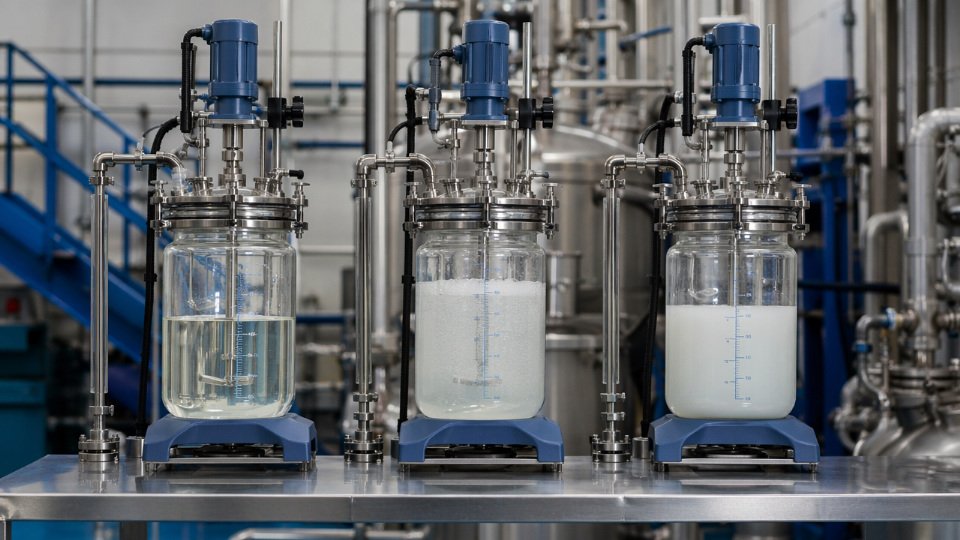
Pre-hydrolyzed silane oligomers are supplied as partially condensed short-chain polysiloxanes — the hydrolysis step has already occurred during manufacture. This changes the dosage calculation in a way that catches engineers off guard. Because the reactive silanol groups are already present and the oligomer molecular weight is higher than the monomer, you can achieve equivalent surface coverage at a lower solution concentration by mass. A 0.3 wt% oligomeric aminosilane solution may deliver the same surface density as 0.8 wt% of the monomeric equivalent.
Oligomeric silanes should be dosed using the same weight percentage guidelines as monomeric silanes.False
Oligomeric silanes are pre-polymerized and have a higher molecular weight and pre-formed silanol content. Using monomeric dosage guidelines for oligomers will typically result in overdose, multilayer deposition, and a brittle or poorly bonded interphase. Always use the active silane content figure from the supplier's technical datasheet and recalculate surface coverage from that basis.
Suppliers of oligomeric silanes publish an active content specification — treat that number as your input to the monolayer coverage calculation, not the total product weight. Skipping that step and treating oligomers as equivalent to monomers is a consistent source of performance variability in coating and composite operations that switch silane grades without recalculating.
Analytical Methods to Measure Surface Coverage and Validate That Target Dosage Was Actually Delivered
Calculating a target dosage from BET surface area and silane molecular footprint is necessary but insufficient. The calculation tells you what to add; it says nothing about what actually bonded. Condensation efficiency varies with mixing shear, temperature, humidity, filler moisture content, and silane reactivity — so closing the loop with measurement is non-negotiable before you lock in a production recipe.
Thermogravimetric Analysis: The Primary Quantitative Workhorse
TGA is the most direct method for measuring organic loading on a treated filler. Run a sample from 25 °C to 900 °C at 10–20 °C/min under air or nitrogen, and three distinct mass-loss regions appear. The first, roughly 25–120 °C, is physisorbed water and residual solvent — not silane. The second region, 300–600 °C, captures decomposition of covalently bonded silane: this is the number you want. The third region above 700 °C reflects inorganic filler decomposition or residual carbonates and is subtracted as baseline.
To convert the mass-loss percentage in the 300–600 °C window to surface coverage:
Coverage (µmol/m²) = [Δm (g) / M_silane (g/mol)] × 10⁶ / [m_filler (g) × BET (m²/g)]
For a precipitated silica with BET around 160–200 m²/g and an aminosilane such as APTES (MW 221 g/mol), a 2% mass loss in that window typically translates to 4–8 µmol/m² — well above monolayer if the filler surface was fully accessible. If you see the onset of decomposition shifting below 250 °C, that is almost always multilayer physisorbed silane oligomers, not chemically grafted coverage. That’s a dosage or process problem, not a measurement artifact.
DRIFTS: Confirming Covalent Bonding Without Drying to Constant Mass
Diffuse reflectance infrared Fourier transform spectroscopy catches what TGA cannot distinguish well: whether the silane is actually covalently bonded to the surface or merely physisorbed. The Si–O–Si network absorption at approximately 1050 cm⁻¹ confirms condensation with surface silanols. For aminosilanes, the N–H bend near 1590 cm⁻¹ must be present; its absence in a treated sample that shows good TGA mass loss is a red flag for incomplete coupling. Vinylsilane-treated fillers should show the C=C stretch at roughly 1600 cm⁻¹ alongside the Si–O–Si band — if the vinyl peak disappears relative to the Si–O band, you have oxidative degradation during processing.
Peak intensity ratios (the Si–O–Si band relative to an internal silica reference band near 800 cm⁻¹) give semi-quantitative coverage data in 10–15 minutes per sample, making DRIFTS a practical screen before committing to TGA runs.
CHN Elemental Analysis: Precise but Requires Complementary Data
Carbon or nitrogen weight percent measured by combustion analysis is accurate to ±0.1–0.3 wt% and back-calculates cleanly to µmol silane/m² when you know the molecular formula and have an independent BET value. For nitrogen-containing silanes like aminosilanes, nitrogen content is the cleaner signal because carbon can come from surface contamination. One constraint: silicon is not measured by standard CHN, so on silicone-free mineral substrates you may need ICP-OES to fully account for the silane silicon contribution.
Contact Angle: Fast Production QC, Not a Quantitative Substitute
Untreated silica powder compressed into a disk shows contact angles below 30° with water. Fully aminosilane-treated silica shifts that to 40–60°, reflecting the amine polarity. Alkylsilane-treated surfaces routinely exceed 90°. These thresholds are reproducible enough for production line QC — a batch that drops below the target range warrants hold and retest — but contact angle alone cannot distinguish between 60% and 100% monolayer coverage with any reliability.
Solution Depletion: Rapid Dosage Iteration Without Full Characterization
Measure silane concentration in the treatment bath before and after contacting the filler. For aromatic silanes, UV-Vis absorbance at the relevant wavelength works well. For aliphatic silanes, total organic carbon analysis is the standard approach. The depleted silane mass divided by filler mass and BET area gives deposited coverage directly — no drying, no TGA turnaround. This method is especially useful during formulation development when you are iterating dosage levels every day and cannot wait 24 hours per data point.
Solution depletion combined with TGA validation provides a faster development cycle than TGA alone during silane dosage optimizationTrue
Solution depletion gives same-day feedback on deposition during wet treatment; TGA then validates the final confirmed recipe, cutting iteration time from days to hours without sacrificing quantitative accuracy on the locked recipe.
Coverage Efficiency: The Number That Actually Closes the Loop
Actual deposited coverage divided by the theoretical monolayer requirement — expressed as a percentage — is the single most useful formulation metric. At 80–110% monolayer coverage, interfacial adhesion and composite mechanical properties are typically optimized for most filled rubber and thermoset systems; multilayer excess adds cost and can act as a weak boundary layer. Below 60%, under-dosing leaves bare surface area that attracts water and degrades long-term adhesion. SiliconChemicals’ formulation lab uses this coverage efficiency window as the acceptance criterion when qualifying a new filler-silane combination, regardless of which analytical method generated the coverage number.
| Method | What It Measures | Turnaround | Quantitative? | Best Use Case |
|---|---|---|---|---|
| TGA | Total chemisorbed organic loading | 1–4 hours | Yes | Recipe qualification |
| DRIFTS | Bonding chemistry confirmation | 15–30 min | Semi | Bonding vs. physisorption check |
| CHN elemental | C or N wt% → µmol/m² | 2–8 hours | Yes | Nitrogen-functional silanes |
| Contact angle | Surface energy shift | 5–15 min | No | Production QC screening |
| Solution depletion | Deposited mass from bath | 1–3 hours | Yes | Dosage iteration in development |
Process Variables That Shift the Effective Dosage Window in Real Manufacturing Conditions
A dosage calculated cleanly on paper — based on BET surface area and monolayer coverage — is a starting point, not an answer. Between the laboratory spreadsheet and the production line sit a half-dozen process variables that each have the power to render your calculated optimum either wasteful or completely ineffective. Engineers who treat dosage as a fixed number rather than a window that shifts with process conditions are the ones chasing adhesion failures and compounding rejects they cannot explain.
Temperature Effects on Hydrolysis and Condensation Kinetics
Raising the treatment temperature from 20 °C to 60 °C roughly halves hydrolysis time for most trialkoxysilanes, which sounds like an advantage — and it is, up to a point. The problem is that self-condensation accelerates in parallel. At elevated temperatures, silanol intermediates find each other faster than they find substrate hydroxyls, producing oligomeric siloxane deposits that consume silane without delivering covalent surface bonding. In continuous spray treatment of precipitated silica — the dominant industrial process for tire-grade silica — typical parameters run inlet dryer temperatures of 120–160 °C with residence times of 3–8 minutes, depending on dryer geometry and airflow. At those conditions, the effective reactive window is narrow. Spray nozzle placement relative to the hot zone matters as much as the nominal dose rate. If silane contacts the hot gas stream before hitting the particle surface, partial pre-condensation is unavoidable, and your actual surface-bonded fraction may be 15–30% lower than the metered quantity suggests.
pH Control in Aqueous Treatment Baths
Trialkoxysilanes hydrolyze fastest in the pH range 3.5–5.5, making acetic acid catalysis the industry standard for aqueous silane bath preparation.True
This is well-established silane chemistry: both acid and base catalyze hydrolysis, but the 3.5–5.5 window minimizes competing condensation reactions while maintaining acceptable hydrolysis rate, and acetic acid is widely used industrially because it is volatile and leaves minimal residue.
Above pH 7, condensation dominates. What you see in the bath is gelation; what you see on the substrate is poor, patchy coverage despite apparent consumption of silane from solution — a classic over-dosage illusion. In practice, add acetic acid to bring the bath to pH 4–5 before introducing the silane, and monitor pH throughout the shift. Bath life for a properly acidified 1–2 wt% trialkoxysilane solution is typically 4–8 hours before hydrolysis products begin self-condensing at a rate that degrades deposition efficiency. Temperature matters here too: a bath running at 40 °C rather than 20 °C cuts that window roughly in half.
Mixing Energy and Shear in Rubber Compounding
In internal mixers — Banbury or intermix configurations — silanization does not happen in a pre-treatment step. It happens in situ, during the mix cycle, at 140–165 °C. The silane is added with the precipitated silica, and the reaction proceeds entirely on the mixer floor. Rotor speed, fill factor, and mixing time all govern silanization conversion. A fill factor below ~0.65 means poor heat transfer and incomplete reaction; above ~0.78, you lose distributive mixing efficiency. The practical consequence is that under-mixing at correct dosage produces the same poor Payne effect reduction and compound viscosity as under-dosing with optimal mixing. These two variables must be co-optimized. Running a dosage screen without holding mixing conditions constant is a waste of compound and a source of false conclusions.
Solvent and Co-Solvent Effects in Coating Applications
In waterborne coating and adhesive primer systems, neat aqueous silane solutions can phase-separate or condense prematurely before uniform substrate wetting is achieved. Adding ethanol or isopropanol at 5–20% by weight of the solution improves silane dispersion and slows premature condensation enough to allow better surface contact time. The practical guideline most coating formulators use is a water-to-alcohol ratio of 5:1 to 10:1 for standard trialkoxysilane working solutions. This co-solvent effect slightly increases the tolerable working concentration before gelation onset, but it does not eliminate the upper limit — it shifts it. Do not interpret co-solvent tolerance as permission to push concentration above 2–3 wt%; the self-condensation ceiling still applies.
Substrate Pre-Treatment and Surface Activation
Plasma, corona, or flame treatment of polymer substrates — polyolefins, fluoropolymers, engineering thermoplastics — increases surface hydroxyl and peroxide density by a factor of 2–5×, depending on treatment intensity and polymer type. That expanded reactive site density means a dosage calibrated for the untreated surface will now deliver sub-monolayer coverage. The silane demand goes up proportionally. Skipping dosage recalculation after introducing a surface activation step is a formulation error that shows up as inconsistent peel strength, particularly at the edges of parts where activation intensity varies. Treat any change to the substrate pre-treatment protocol as a trigger for a full dosage re-optimization, not a minor processing note.
Curing and Drying Cycle After Silane Application
The condensation reaction between surface-bonded silanols and adjacent silanol groups — the step that creates a durable cross-linked interface layer — requires thermal energy to complete. Typical post-cure conditions for most trialkoxysilane systems are 100–120 °C for 10–30 minutes, with the lower end of that range suitable for aminosilanes and the higher end necessary for bulkier organosilanes with slower condensation kinetics. An under-cured treatment, even at correct nominal dosage, leaves a significant fraction of silanol groups unreacted. In humid service conditions, those groups hydrolyze back, the interface weakens, and the failure mode looks like adhesion degradation over time — a warranty problem, not a raw material problem. The curing step is not downstream housekeeping; it is the final reaction stage in the dosage equation. Shortening cycle time to meet throughput targets without verifying condensation completeness is a common root cause of field failures that takes months to surface.
Systematic Experimental Design Protocols for Finding the Optimal Dosage in a New Application
When you encounter a new substrate-silane-matrix combination, intuition and literature precedent get you to the right order of magnitude. A structured experimental protocol gets you to the right number — the one you can defend to a process engineer, justify to a procurement manager, and reproduce on a 10-tonne internal mixer six months later.
Step 1 — Theoretical Monolayer Calculation as Your Center Point
Start with the math before you touch a mixing mill. For a precipitated silica at 160 m²/g loaded at 30 phr in an SBR compound, using TESPT (bis[3-(triethoxysilyl)propyl] tetrasulfide, MW 538.9 g/mol, molecular footprint ~0.6 nm²):
Silane molecules needed per gram of silica = (160 m²/g × 10¹⁸ nm²/m²) / 0.6 nm²/molecule = 2.67 × 10²⁰ molecules/g
Converting to moles: 2.67 × 10²⁰ / 6.022 × 10²³ = 4.43 × 10⁻⁴ mol/g silica
Mass of TESPT per gram of silica = 4.43 × 10⁻⁴ mol × 538.9 g/mol = 0.239 g TESPT/g silica, or roughly 23.9 wt% on filler.
At 30 phr silica in 100 g rubber, silica mass = 30 g, so theoretical TESPT = 30 × 0.239 = 7.17 g per 100 g rubber, or 7.17 phr. This sits comfortably within the 6–12 wt% silane-on-silica range typical for precipitated silica systems. That 7.17 phr is your center point. Round to 7.0 phr for practical batching. Everything else anchors to this number.
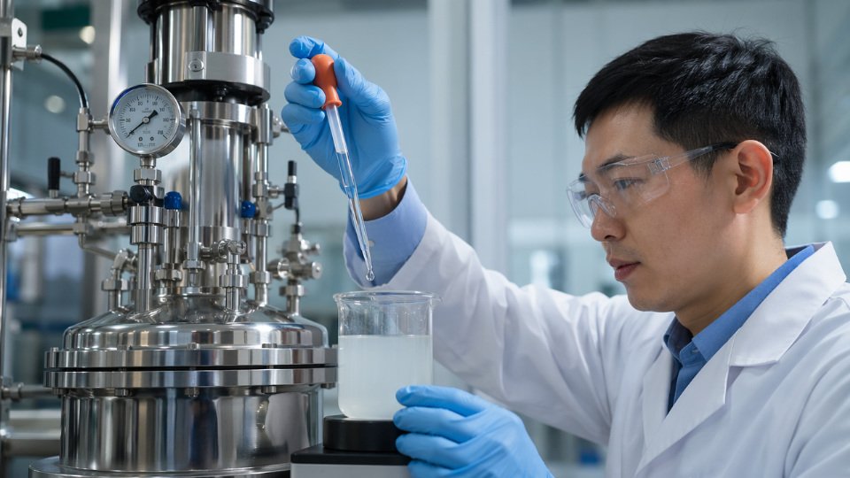
Step 2 — Five-Level Screening Before Any Factorial Design
Run a single-factor screen at 50%, 75%, 100%, 125%, and 150% of theoretical monolayer — in this case, roughly 3.5, 5.25, 7.0, 8.75, and 10.5 phr TESPT. Keep every other variable fixed: mixer fill factor, dump temperature, rotor speed, mix time. Engineers routinely skip this step and jump straight to a full factorial or Taguchi array. The consequence is a well-executed factorial design sitting in entirely the wrong concentration space, producing data that cannot identify a true optimum. A five-level screen costs five batches; a misdirected factorial easily costs twenty.
Step 3 — Choose Response Variables That Reflect End-Use Reality
For rubber composites, the Payne effect (ΔG’ measured by rubber process analyzer across 0.56–100% strain sweep) is the most direct indicator of filler network disruption and silane efficacy — more diagnostic than hardness or Mooney viscosity alone. A well-silanized silica compound at optimum loading typically shows a substantially reduced ΔG’, confirming that the filler-filler network has been displaced by filler-polymer coupling.
The Payne effect amplitude (ΔG') decreases monotonically as silane surface coverage approaches a complete monolayer in precipitated silica/SBR systems.True
As silane coverage increases toward monolayer completion, silanol groups on the silica surface are progressively blocked, reducing polar filler-filler interactions and the strain-dependent modulus drop characteristic of the Payne effect. This is well-documented in rubber physics literature and confirmed by RPA measurements.
For adhesive and coating applications, use cross-cut adhesion (ISO 2409), tensile lap shear, and humidity-cabinet resistance. For glass-fiber-reinforced thermoplastics, notched Izod impact and tensile modulus both respond clearly to interfacial quality and are fast to measure.
Step 4 — Locate the Diminishing-Returns Inflection Point
Plot each response variable against dosage. The curve will flatten — sometimes sharply, sometimes gradually. Your economic optimum sits 5–15% above that inflection point, not at the absolute peak response. Silane cost scales linearly with addition level; performance improvement does not. Chasing the last 2–3% of tensile strength by adding 30% more silane rarely passes a cost-benefit calculation once you account for raw material cost, increased volatile organic compound emissions during mixing, and potential plasticization effects from excess unreacted silane.
Step 5 — Validate With Accelerated Aging, Not Just Short-Term Mechanical Data
A freshly compounded or cured sample can look excellent at any dosage within a broad range. Interfacial bond durability under moisture and thermal stress is a far stricter filter. Include 72-hour water immersion, 1000-hour salt spray per ISO 9227, or 7-day autoclave aging at 121 °C and 100% relative humidity, depending on the end-use environment. Under-dosed systems that pass day-one adhesion tests routinely fail at the 500-hour mark in salt spray. This is where many field warranty problems originate — optimized on short-term data, never validated for durable bonding.
Step 6 — Scale-Up Validation and Process Capability
The lab optimum must survive production tolerances. Verify that your silane addition system — whether liquid injection, pre-blended masterbatch, or dry powder — can deliver the target dosage within ±10% across normal production variation. Calculate Cpk for the silane addition step; a Cpk below 1.33 means a meaningful fraction of your production batches will run outside the validated dosage window. If process capability is marginal, shift your set point upward toward the plateau region, where a ±10% dosage swing produces negligible performance variation. Building that flat region into the target is not over-engineering — it is the difference between a process that works in the lab and one that holds specification on the factory floor.
Application-Specific Dosage Reference Ranges Across Rubber, Coatings, Adhesives, and Polymer Composites
Calculated theory gets you to the right order of magnitude. Documented industry ranges get you to a working starting point in days rather than weeks. The figures below come from formulation practice across high-volume production environments; treat them as calibrated starting brackets, not fixed recipes, because the final optimum always depends on your specific filler surface area, mixing equipment, and cure chemistry.
Tire and Technical Rubber Compounds
EU fuel-efficiency labeling has pushed passenger tire tread silica loadings above 70 phr in most competitive compounds, which makes silane stoichiometry genuinely consequential — excess TESPT (Si69) contributes to premature Mooney scorch, while a shortfall leaves unbound silica that drives rolling resistance back up and degrades wet grip durability. The accepted working range is 6–12 wt% TESPT on silica, with the upper end reserved for high-surface-area precipitated silicas (BET ≥ 175 m²/g) mixed at dump temperatures approaching 155 °C.
Mercaptopropyltriethoxysilane (MPTMS) reacts faster than TESPT — useful when mixing cycle time is constrained — but its free thiol accelerates cure, so it is typically used at 4–8 wt% on silica paired with a delayed-action accelerator system to preserve scorch safety. Vinyltrimethoxysilane in peroxide-cured HCR silicone rubber sits in a different register entirely: 0.5–2.0 phr on fumed silica, where the function is in-situ crosslink density control rather than surface coverage in the classical sense.
Thermoset Composites and Glass Fiber Sizing
Glass fiber sizing is a dilute aqueous system, which changes the calculation entirely. Aminosilane (APTES, A-1100 type) is applied from bath concentrations that land 0.1–0.5 wt% on the fiber, translating to a dry LOI contribution of roughly 0.05–0.2 wt% of finished strand weight depending on fiber tex and bath pickup. For epoxy matrix systems, epoxysilane (GPTMS, A-187 type) at 0.2–0.8 wt% in the size formulation gives better resin-to-fiber bond retention under humid aging than aminosilane alone, which is why many structural composite sizing blends use both. Methacrylsilane (A-174 type) for polyester and vinyl ester matrix sits tighter, 0.1–0.4 wt% in size; going higher rarely improves ILSS and can plasticize the sizing film, reducing strand integrity on the creel.
Waterborne Coatings and Corrosion-Inhibiting Primers
In waterborne coatings, silane acts as an adhesion promoter rather than a bulk modifier, so dosage is expressed relative to total formulation weight. Aminosilane and epoxysilane additives fall in the 0.2–1.0 wt% range for improving adhesion to glass, aluminum, and galvanized steel. Bis-amino silane oligomers used in corrosion-inhibiting thin-film primers require 1–5 wt% active content on the metal surface area basis — and this is where in-bath pH control (targeting 4.0–5.0) becomes as important as the dosage number itself.
Thermoplastic Compounding
Vinylsilane for moisture-cure crosslinking of polyethylene runs 1.5–3.0 wt% of polymer weight, grafted under peroxide in a reactive extrusion process; residence time in the extruder barrel directly affects graft efficiency, making screw design a secondary variable. Aminosilane-treated wollastonite or kaolin for polyamide reinforcement sits at 0.5–1.5 wt% on filler, where the target is improving notched Charpy impact retention after 72-hour humidity exposure. Chlorosilane surface treatment of talc for polypropylene is the narrowest window: 0.3–0.8 wt% on filler, because chlorosilane reacts instantaneously and over-treatment leaves HCl residues that degrade PP molecular weight during compounding.
Sealants and Adhesives
Alkylalkoxysilane adhesion promoters in one-part silicone or hybrid sealants are effective at just 0.1–0.5 wt% of total formulation — a small number with a disproportionate effect on peel strength on difficult substrates like powder-coated aluminum. Bis-silyl urea crosslinkers in moisture-cure polyurethane require 0.5–2.0 wt%, with the optimum shifting upward in high-humidity climates where competitive hydrolysis consumes a fraction of the available silane before crosslinking occurs. SMP adhesives, where silane terminal groups are built into the polymer backbone, operate on a molar basis: 3–8 mol% terminal silane functionality is the range that balances open time against final cohesive strength.
TESPT at 6–12 wt% on silica is the accepted industry dosage range for passenger tire tread compounds using precipitated silica above 70 phr loadingTrue
This range is consistent with published tire formulation literature and commercial practice validated by rheological and dynamic mechanical analysis; it accounts for variation in silica BET surface area and mixing dump temperature.
Consolidated Dosage Reference Table
| Application | Substrate / Filler | Silane Type | Typical Dosage Range | Primary Performance Metric | Key Process Note |
|---|---|---|---|---|---|
| Passenger tire tread | Precipitated silica (≥175 m²/g) | TESPT (Si69) | 6–12 wt% on silica | Rolling resistance, wet grip | Keep dump temp 145–155 °C; above 160 °C risks premature crosslinking |
| Technical rubber (fast-cure) | Precipitated silica | MPTMS | 4–8 wt% on silica | Scorch safety, cure rate | Pair with delayed accelerator; free thiol accelerates vulcanization |
| HCR silicone rubber | Fumed silica | Vinyltrimethoxysilane | 0.5–2.0 phr on silica | Crosslink density, compression set | Dose controls network density, not just surface coverage |
| Glass fiber sizing (epoxy matrix) | E-glass fiber | APTES + GPTMS blend | 0.1–0.8 wt% in size bath | ILSS, wet retention | Bath pH 3.5–4.5; hydrolysis before fiber contact essential |
| Glass fiber sizing (polyester matrix) | E-glass fiber | Methacrylsilane (A-174) | 0.1–0.4 wt% in size bath | Flexural strength retention | Excess plasticizes sizing film; stay at lower end for woven fabric |
| Waterborne adhesion primer | Glass, aluminum, galvanized steel | Aminosilane or epoxysilane | 0.2–1.0 wt% of formulation | Cross-cut adhesion, humidity resistance | Adjust pH to 4.0–5.0 before addition to prevent oligomerization |
| Corrosion-inhibiting thin-film primer | Steel | Bis-amino silane oligomer | 1–5 wt% active on surface | Salt-spray hours, underfilm corrosion | Film thickness 50–200 nm; bath concentration controls deposition rate |
| Moisture-cure PE crosslinking | HDPE / LLDPE | Vinylsilane (grafted) | 1.5–3.0 wt% of polymer | Gel content, hot-set elongation | Screw L/D and residence time govern graft efficiency as much as dosage |
| Polyamide reinforcement | Wollastonite / kaolin | Aminosilane | 0.5–1.5 wt% on filler | Impact retention after humid aging | Pre-treatment preferred over in-situ for consistent coverage |
| Polypropylene compounding | Talc | Chlorosilane | 0.3–0.8 wt% on filler | Stiffness, surface finish | Instantaneous reaction — over-treatment leaves HCl; ventilation mandatory |
| One-part silicone sealant | Powder-coated aluminum, glass | Alkylalkoxysilane | 0.1–0.5 wt% of formulation | Peel adhesion, weathering durability | Low dose, high impact; no benefit above 0.5 wt% on most substrates |
| Moisture-cure polyurethane | Various | Bis-silyl urea crosslinker | 0.5–2.0 wt% of formulation | Cohesive strength, open time | Upper end of range needed in tropical (>80% RH) production environments |
| SMP adhesive | Various | Silane-terminated polymer | 3–8 mol% terminal groups | Open time vs. final strength balance | Backbone silane content set at synthesis; field adjustment not possible |
Economic Optimization: Balancing Silane Cost Against Performance and Regulatory Constraints
Optimal dosage is not the concentration that maximizes bond strength on a tensile bar. It is the concentration that minimizes total cost per kilogram of finished compound while staying inside regulatory and process constraints. Those two targets rarely sit at the same point on the curve, and engineers who treat dosage purely as a performance variable routinely leave money on the table — or create compliance problems they cannot bill back to the customer.
Building the Total Cost Curve
Think of total silane-related cost per kilogram of compound as the sum of four components: silane raw material cost (rising linearly with dosage), scrap and rework cost (falling steeply as dosage increases from deficiency toward adequacy, then flattening), energy cost (roughly flat across the practical dosage range — mixing and drying energy does not change meaningfully between 0.8 wt% and 1.2 wt% silane on filler), and waste treatment cost (rising with dosage because excess silane that does not bond to the substrate ends up as VOC emissions, alcoholic condensate requiring recovery, or aqueous effluent requiring pH correction and COD treatment).
The true optimum is the minimum of the summed curve. In most filled rubber and coating applications, that minimum sits 10–20% below the performance plateau — meaning the last increment of silane that measurably improves bond strength costs more in waste and treatment than it returns in quality. Identifying that plateau requires the experimental dose-response data described in earlier sections; the cost overlay converts the data into a business decision.
How China-Based Supply Shifts the Optimum
China accounts for over 60% of global organosilicon monomer capacity, and vertically integrated manufacturers within those clusters — from chlorosilane synthesis through alkoxysilane functionalization — carry substantially lower conversion and logistics costs than European or North American producers. For triethoxysilane-based products, landed cost differentials of 15–35% are realistic depending on order volume, incoterms, and destination port; the exact figure depends on freight rates, import duty structure, and whether the buyer can consolidate container loads.
Vertically integrated Chinese silane manufacturers can offer 15–35% lower landed cost on triethoxysilane-based coupling agents compared to equivalent European or North American products.True
This reflects the structural cost advantage of China's integrated organosilicon clusters, where chlorosilane feedstock, distillation, and functionalization occur within the same industrial zone, reducing intermediate logistics and energy cost. The range is wide because actual savings depend on order size, freight lane, and currency conditions.
That cost advantage does not mean the answer is simply to use more silane. It means the cost-optimum point shifts slightly toward higher surface coverage targets for the same budget — enabling formulators to close the gap between theoretical monolayer demand and practical process losses without budget penalty.
Regulatory Ceilings Are Hard Constraints, Not Guidelines
REACH substance restrictions, EPA 40 CFR Part 63 NESHAP rules, and EU Industrial Emissions Directive 2010/75/EU all impose VOC emission ceilings on surface treatment operations. Before beginning any performance optimization, calculate the maximum permissible silane addition rate from your facility’s ventilation capacity, exhaust abatement efficiency, and the silane’s vapor pressure at process temperature. That number is your hard upper dosage limit. Performance optimization happens within the space below it, not independently of it.
Batch Consistency as a Hidden Economic Variable
An optimal average dosage held at a coefficient of variation above 15% delivers worse real-world performance than a dosage set 10% lower but controlled to CV below 5%. Variability means some batches are under-treated — generating adhesion failures, warranty claims, and rework — while others are over-treated, generating waste treatment cost and potential compliance exceedances. Gravimetric dosing systems with load-cell verification, combined with inline viscosity or density monitoring for liquid silane streams, typically reduce CV to 3–8% and pay back capital cost within 12–24 months in scrap reduction alone, depending on compound value and batch size.
Silane Utilization Efficiency as a KPI
Track grams of silane deposited on substrate divided by grams of silane added to the process. In spray-dry filler treatment, utilization typically runs 55–75%; in controlled aqueous bath treatment with residence time management, it reaches 85–95%. A 10-percentage-point improvement in utilization at constant performance is always cheaper than a 10% dosage increase: it reduces raw material consumption, lowers VOC load, cuts effluent volume, and keeps you further from regulatory ceilings. Improving utilization requires attention to spray droplet size, filler surface temperature, residence time, and pH control — process variables covered earlier — but the economic incentive to optimize them is clearest when expressed as a utilization KPI tracked batch by batch.
Troubleshooting Guide: Diagnosing Dosage-Related Failures in Production
When a silane-treated system underperforms, the instinct is often to blame the silane grade or the substrate batch. In practice, the root cause is dosage-related more often than not — either the amount applied, the concentration of the treatment solution, or the mismatch between calculated and delivered coverage. The diagnostic logic below maps observable symptoms to specific failure mechanisms so you can narrow the root cause within one shift rather than weeks of scatter-shot reformulation.
Poor Wet Adhesion or Adhesion Loss After Humidity Exposure
Bare substrate patches are the first suspect. When coverage falls below roughly 60% of the theoretical monolayer, moisture finds unprotected surface hydroxyl sites and displaces the organic matrix. TGA on the treated filler or substrate will show a mass-loss step in the 200–450 °C window that is proportionally smaller than expected for full coverage; anything short of that threshold is a reliable indicator of under-dosage.
Wrong functional group selection produces a similar symptom but for a different reason — the silane bonds to the substrate but cannot react with the matrix, so the interface hydrolyzes under humidity loading regardless of coverage level. Distinguish this from under-dosage by comparing dry versus wet lap-shear strength: under-dosage degrades both, while functional group mismatch degrades wet strength disproportionately.
Low post-application cure temperature is a process variable that compounds either problem. Siloxane bond densification below 100 °C is slow; extending cure at 110–120 °C for an additional 20–30 minutes typically recovers 10–20% of interfacial bond strength in epoxy and polyurethane systems. Increasing dosage by roughly 25% is a reasonable first corrective step, but always verify treatment bath pH sits in the 3.5–5.5 window for trialkoxysilanes — outside that range, hydrolysis is either incomplete or the silanol condenses in solution before reaching the surface.
Compound Hardness Increase and Mooney Viscosity Spike
Over-dosage in filled rubber is the classic scenario here. Excess silane forms siloxane oligomers that bridge filler particles, creating a crosslinked filler network before vulcanization even begins. The Payne effect — the amplitude of storage modulus drop from low to high strain in dynamic mechanical testing — is the right diagnostic. A high Payne effect alongside elevated Mooney viscosity points to filler networking from residual silanol activity or silane over-condensation, not to matrix crosslink density. Reduce dosage by 15–20% and verify that mixing temperature stays above 140 °C for TESPT-type silanes, since the coupling reaction needs thermal activation to proceed before the silanization window closes.
Surface Blooming or White Deposit on Cured Parts
This is almost always excess unreacted silane — particularly amino and long-chain alkyl silanes — migrating to the surface as the part cools. Coverage above 150% of the theoretical monolayer is the typical threshold where bloom becomes visible. The fix is dosage reduction to stay within the monolayer band, and if the process cannot hold tight enough tolerances, a post-treatment wash step with dilute isopropanol removes the mobile excess before cure.
Foaming During Mixing or Coating Application
Rapid alcohol release from trialkoxysilane hydrolysis is the direct cause. At concentrations above 2 wt% in aqueous solution without a co-solvent buffer, ethanol or methanol evolution outpaces surface absorption. Switch to a pre-hydrolyzed silane oligomer, which has already released most of the alcohol, or reduce working concentration below 1.5 wt% and add antifoam at 0.05–0.1 wt%. Pushing concentration without managing the alcohol release rate is a common scaling mistake when moving from lab to pilot batches.
Inconsistent Lot-to-Lot Mechanical Properties at Constant Silane Addition
BET surface area of commercial precipitated silica can vary ±15% between production lots from the same supplier. A fixed weight-ratio silane addition means actual surface coverage swings by the same margin, which translates directly into scattered tensile or adhesion data. The solution is to request BET values on each filler Certificate of Analysis and normalize silane addition to actual surface area rather than filler weight. This single procedural change has eliminated unexplained lot-to-lot scatter in multiple compounding operations.
Normalizing silane dosage to measured BET surface area of each filler lot, rather than using a fixed weight ratio, is a validated method for reducing lot-to-lot mechanical property variance in filled polymer systems.True
BET-based dosage normalization directly accounts for batch variation in filler surface area, which is the primary driver of coverage inconsistency. This approach is standard in technical rubber and coating formulation practice and is supported by surface chemistry stoichiometry.
Structured Diagnostic Reference
| Observed Symptom | Most Likely Dosage Root Cause | Diagnostic Test | Corrective Action | Prevention |
|---|---|---|---|---|
| Wet adhesion loss after humidity exposure | Under-dosage; coverage below 60% monolayer | TGA mass loss in 200–450 °C range; wet vs. dry lap-shear ratio | Increase dosage 25%; verify bath pH 3.5–5.5; extend cure at 110–120 °C | Calculate dosage from BET; confirm pH before each batch |
| Mooney viscosity spike; compound hardness increase | Over-dosage causing filler network via silane condensation | Payne effect (dynamic strain sweep); compare to reference compound | Reduce dosage 15–20%; verify mixing temperature ≥140 °C for TESPT | Set dosage ceiling relative to filler surface area |
| Surface bloom or white deposit | Excess unreacted silane above 150% monolayer | Visual inspection; wipe test; XPS or FTIR on deposit | Reduce to monolayer-equivalent dosage; add post-cure wash step | Monitor coverage by TGA on treated filler samples |
| Foaming during mixing or application | Over-concentrated solution releasing alcohol too fast | Measure foam volume at working concentration; titrate solvent content | Reduce to ≤1.5 wt%; use pre-hydrolyzed oligomer; add antifoam 0.05–0.1 wt% | Pre-test concentration at lab scale before scale-up |
| Inconsistent lot-to-lot properties | Filler BET variation (±15%) with fixed silane weight ratio | BET measurement on each incoming lot; plot silane/m² vs. property | Normalize silane addition to BET surface area per lot | Require BET on every filler CoA; build it into the dosage calculation |
Frequently Asked Questions About Silane Coupling Agent Dosage and Concentration
What is the simplest formula to calculate silane coupling agent dosage on a filler?
The baseline calculation is:
Grams of silane per gram of filler = (S × M) / (A_f × N_A × 10¹⁸)
where S = BET surface area (m²/g), M = molecular weight of the silane (g/mol), A_f = molecular footprint (nm²), and N_A = Avogadro’s number (6.022 × 10²³).
For APTES (3-aminopropyltriethoxysilane, M = 221 g/mol) on a 200 m²/g fumed silica with a footprint of roughly 0.40 nm², this resolves to approximately 1.1 wt% silane on filler — a workable starting point, not a guaranteed optimum. That figure shifts if your silica has a different surface area lot-to-lot, which BET certification from your filler supplier should confirm before you fix a production recipe. Treat the formula output as the lower bound of a bracket, then bracket upward by 20–30% in your first trial series to account for incomplete hydrolysis and steric inefficiency under real mixing conditions.
Can I use the same dosage for different silane types on the same filler?
No, and conflating them is one of the more common formulation errors on the plant floor. Molecular footprint varies significantly across silane families. Aminosilanes such as APTES occupy roughly 0.40 nm² per molecule; bis-silyl polysulfide silanes (TESPT-type, widely used in silica-filled tire compounds) occupy 0.8–1.0 nm² because the molecule is bulkier and the sulfur bridge adds steric demand. Same filler, same target coverage, meaningfully different weight-based loading. Hydrolysis rate compounds the difference further — short-chain vinyltrimethoxysilanes hydrolyze within minutes under mild acid conditions, while longer-chain or sterically hindered silanes may need 15–30 minutes to reach equivalent silanol availability. Swapping silane types without recalculating and retesting the dosage will either leave surface sites unoccupied or deposit excess condensed silane that acts as a plasticizer or adhesion disruptor.
How do I know if my silane dosage is too high without lab equipment?
Several process signals show up before any analytical instrument is involved. In rubber compounding, over-dosed silica systems frequently exhibit higher-than-expected Mooney viscosity early in mixing because excess condensed silane creates a gel-like interparticle network. Surface blooming — a white or oily film on cured part surfaces — indicates silane migrating out of the matrix after cure. Persistent alcoholic odor (ethanol or methanol, depending on the alkoxy group) in cured or semi-cured parts means incomplete reaction; the unreacted species is volatilizing. Foaming during high-shear mixing is another red flag, caused by rapid alcohol release from hydrolysis under heat. Any one of these warrants a dosage reduction trial and a call to your silane supplier’s technical team before the next production run.
Excess silane dosage in silica-filled rubber compounds raises Mooney viscosity and can cause surface blooming in cured parts.True
Unreacted or over-condensed silane acts as a plasticizer or migrates to the surface post-cure; elevated Mooney viscosity in over-dosed silica compounds is well-documented in tire compound development literature.
Does silane concentration in a primer solution follow the same rules as filler surface treatment dosage?
The underlying chemistry is the same — silanol groups forming covalent bonds with surface hydroxyls — but the engineering constraints are entirely different. Filler treatment is a three-dimensional surface-area problem measured in µmol/m². Primer application is a two-dimensional film deposition problem where the substrate surface area is fixed and low. Working concentrations for primer solutions typically run 0.1–2.0 wt% in water or water-alcohol blends, and above a threshold concentration (often around 1.0–1.5 wt% for monomeric trialkoxysilanes) additional silane does not improve adhesion; it builds up as a poorly cross-linked multilayer that can actually reduce bond strength. Application method — wipe, spray, or dip — controls deposition uniformity far more than concentration does once you are above that threshold. Dip application on porous substrates and spray on smooth metals behave differently even at identical solution concentration.
What shelf life and storage conditions affect the usable concentration of a silane coupling agent solution?
Freshly prepared aqueous solutions of monomeric trialkoxysilanes should be used within 4–8 hours. Hydrolysis begins immediately on contact with water, and condensation follows; by the time a solution is 12 hours old at room temperature and near-neutral pH, a significant fraction has polymerized into oligomers or colloidal particles that will not bond to the substrate uniformly. Sealed, anhydrous bulk silane stored at 5–25 °C away from moisture carries a practical shelf life of 12–24 months for most commercial grades. The exception worth knowing: oligomeric pre-hydrolyzed silane products, which are intentionally partially condensed during manufacture, show bath life of 24–72 hours in dilute aqueous solution because the oligomeric structure is already past the rapid early condensation phase and more stable. These are particularly useful in continuous dip-coating operations where frequent bath preparation is impractical.
How does SiliconChemicals support customers in optimizing silane dosage for new applications?
SiliconChemicals’ technical service laboratory offers TGA-based surface coverage analysis on treated filler samples, allowing customers to confirm whether a given dosage actually delivered a monolayer, a sub-monolayer, or excess deposition before committing production trials. Customers can submit filler samples along with application requirements — matrix type, cure chemistry, target mechanical properties, processing temperatures — and receive a dosage recommendation report backed by test data. Formulation development support covers rubber, coatings, and adhesive systems. For procurement teams evaluating silane grades across suppliers, SiliconChemicals can provide comparative coverage data on the same filler lot, removing a common source of cross-supplier variability from the qualification decision.