Picking the wrong silicone oil for an electronics application is one of those mistakes that doesn’t announce itself immediately. A fluid with inadequate dielectric strength lets a high-voltage module arc under load; one with the wrong viscosity either starves a cooling channel or creates enough drag to overheat a rotating assembly. Either way, the failure shows up as a warranty return, a line stoppage, or — in the worst case — a field incident that triggers a regulatory review. The fluid specification is rarely the first thing engineers scrutinize, which is exactly why it keeps causing problems.
Choose silicone oil for electronics by matching viscosity to your heat-transfer or lubrication duty (0.65 cSt to 1,000,000 cSt at 25°C is the available range), confirming dielectric strength meets your voltage clearance requirements (PDMS fluids typically deliver 15–20 kV/mm), and verifying the fluid’s continuous service temperature covers your worst-case operating environment, which for most electronics-grade silicone oils runs from −60°C up to around +200°C continuously.
What makes this harder in practice is that those three parameters interact. A low-viscosity fluid that gives you excellent thermal conductivity in a liquid cooling loop may not have the film strength you need if there’s any mechanical contact in the same assembly. And the purity grade — which doesn’t appear in most datasheets prominently — determines whether the fluid is safe around sensitive optical sensors or bare copper traces. That’s where most procurement decisions go quietly wrong.
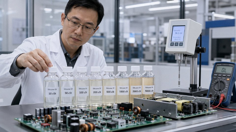
Decoding Silicone Oil Chemistry: PDMS, Phenyl, and Functional Variants Explained
The backbone of virtually every electronics-grade silicone oil is polydimethylsiloxane — PDMS for short. The structure is straightforward: alternating silicon and oxygen atoms form the main chain (Si–O–Si–O), with two methyl groups hanging off each silicon. That methyl-saturated surface is what gives PDMS its near-legendary hydrophobicity. Water beads off it. Moisture-driven leakage currents — a genuine failure mode on densely populated PCBs — find very little foothold. Surface tension sits around 20–21 mN/m depending on viscosity grade, which is lower than most transformer oils and far below water, so the fluid wets and fills fine-geometry gaps without aggressive capillary force that could shift small components.
The Si–O bond itself is unusually stable. Bond dissociation energy is high, thermal oxidation onset is slow, and the backbone doesn’t absorb UV the way hydrocarbon chains do. That’s not marketing language — it’s why PDMS has been the default dielectric coolant for high-voltage switching equipment for decades.
Phenyl-Modified Grades: When Methyl Isn’t Enough
Replace some of those methyl side groups with phenyl rings and the fluid changes character in useful ways. Phenyl groups are bulkier and more polarizable, which raises the refractive index — relevant if you’re encapsulating LEDs or optical sensors where index matching reduces internal reflection losses. More practically for electronics engineers: phenyl content pushes thermal stability upward, typically allowing continuous use to around 250°C and short excursions toward 280–300°C, compared to roughly 200°C continuous for straight PDMS.
Aerospace avionics and satellite electronics care about this. Components in proximity to power electronics or in poorly ventilated enclosures can see sustained temperatures that would gradually degrade a standard PDMS fluid over a service life measured in years. Phenyl grades also resist gamma and particle radiation better than pure methyl silicones — the aromatic rings absorb radiation energy without breaking the backbone as readily. For ground-based electronics, this barely matters. For anything going near a reactor instrumentation system or high-altitude payload, it’s worth specifying.
The trade-off is pour point and viscosity behavior at low temperature. Higher phenyl content stiffens the fluid in the cold; in some grades the pour point rises above −40°C. If your assembly goes through arctic shipping or outdoor temperature cycling, check the low-temperature kinematic viscosity, not just the room-temperature spec.
Functional Fluids: Amino, Epoxy, Carbinol, and Fluorosilicone
Functional silicones add reactive groups along the chain — amino, epoxy, carbinol, or others — and each one is designed for a narrow job. In electronics, the one that comes up most often in real procurement decisions is fluorosilicone. Fluorosilicone replaces some methyl groups with trifluoropropyl groups, which dramatically improves resistance to hydrocarbon fuels, oils, and aggressive solvents. Fuel-contact sensor assemblies in automotive and aerospace applications routinely spec fluorosilicone because standard PDMS swells and softens in jet fuel or transmission fluid. It’s not a subtle failure mode — swollen potting material can unseat a sensor element entirely.
Amino and epoxy functional fluids turn up as coupling agents or adhesion promoters rather than bulk dielectric fluids. Useful for bonding silicone encapsulants to metal substrates, but not something you’d specify as a coolant.
Cyclic Oligomers: The Problem Nobody Talks About Until They Have a MEMS Failure
Linear PDMS is synthesized through ring-opening polymerization, and the process always leaves behind some cyclic oligomers — primarily D4 (octamethylcyclotetrasiloxane), D5, and D6. These are low-molecular-weight, volatile, and they migrate. In open-air electronics, they’re mostly harmless. In sealed MEMS devices, optical sensors, or semiconductor fab environments, they are a serious contamination risk. Cyclic siloxanes deposit on mirror surfaces, quartz oscillators, contact interfaces — anywhere they can condense — and the residue degrades performance in ways that are genuinely difficult to diagnose without GC-MS analysis.
Standard industrial PDMS fluids are safe to use in MEMS sensor assemblies without checking cyclic contentFalse
Standard grades can contain several hundred ppm of D4/D5/D6 cyclics. MEMS environments and optical sensor housings require low-cyclic or stripped grades with specified cyclic content limits, typically below 50–100 ppm total, confirmed by GC analysis on the certificate of analysis.
Reputable suppliers offer stripped or low-cyclic grades and will confirm limits on the CoA. If the datasheet doesn’t mention cyclic content, ask for it before you qualify the fluid.
Reading a Certificate of Analysis Without Getting Fooled
A CoA for electronics-grade silicone oil should show kinematic viscosity at 25°C (and ideally at a second temperature to confirm viscosity index), refractive index at 25°C, flash point, and — for any sensitive application — cyclic siloxane content by GC. Some suppliers also report ionic impurity levels (sodium, chloride, potassium), which matter if the fluid contacts bare die or wire bond interfaces. Flash point is often 280–300°C+ for mid-to-high viscosity PDMS grades, but drops meaningfully for very low viscosity fluids below about 5 cSt; don’t assume a silicone fluid is non-flammable without checking the actual value for the grade you’re buying.
Refractive index gives you a fast sanity check on phenyl content and base polymer purity. Pure PDMS typically reads around 1.400–1.404 at 25°C. Higher values indicate phenyl modification. If a supplier ships a drum labeled as straight PDMS and the refractive index comes in at 1.43, something is off — either mislabeling or blending, both of which warrant a conversation before you put it into production.
Matching Viscosity Grade to Your Specific Electronic Application
Viscosity is the first number most engineers look at on a silicone oil datasheet, and it’s frequently the one they get wrong — not because they misread it, but because they read it at 25°C and never check what happens at the actual operating extremes of their system. The practical selection logic breaks down cleanly by application family, but the temperature-viscosity relationship cuts across all of them and deserves a worked example before you commit to a purchase order.
Low-Viscosity Grades: 0.65–10 cSt
This range is where immersion cooling lives. Server blade systems, power modules, and increasingly high-density GPU clusters running direct-liquid-immersion all pull from the 1–5 cSt bracket, sometimes down to 0.65 cSt where you need maximum heat transfer coefficient and minimal pumping energy. The trade-off is real and worth flagging explicitly: fluids in this range carry vapor pressures that are meaningfully higher than their thicker cousins, which means evaporative loss inside partially open or warm enclosures is not hypothetical. In a sealed two-phase immersion tank you can manage this. In a spray-cooling rig with any bypass, you will lose fluid volume over months and your thermal performance will drift before anyone notices.
Penetration into tight fin arrays and under BGA packages is excellent at these viscosities, which is the whole point. Just account for fluid top-up cycles in your maintenance schedule, and make sure your facility handles the vapor concentration — low-viscosity PDMS is not acutely hazardous but it will leave a film on everything in the room over time.
Mid-Viscosity Grades: 50–500 cSt
Transformer impregnation, capacitor filling, and high-voltage assembly potting are the workhorses here. This bracket gives you enough surface tension reduction and capillary penetration to wick into wound windings or ceramic layer gaps, while retaining the fluid under vibration loading without creep. A 100 cSt fluid will stay where you put it in a sealed capacitor; a 5 cSt fluid at elevated temperature may not. The dielectric performance of PDMS across this range — typically 15–20 kV/mm, depending on purity grade and the presence of dissolved ionic contaminants — holds up well, compared to mineral oil at roughly 10–15 kV/mm.
PDMS fluids in the 50–500 cSt range typically achieve 15–20 kV/mm dielectric strength, outperforming standard mineral oils rated at 10–15 kV/mm.True
These ranges are consistent with published data from major silicone fluid manufacturers (Dow, Shin-Etsu, Momentive) for electronic-grade PDMS, and the mineral oil benchmark aligns with IEC 60296 transformer oil specifications.
High-Viscosity Grades: 1,000–60,000 cSt
Gyroscope damping, shock-mounted PCB assemblies, and mechanically tuned RF elements all need fluids that stay viscous under dynamic loads. The critical engineering parameter here — the one that bites people in wide-temperature deployments — is the viscosity-temperature coefficient (VTC). PDMS has an unusually flat VTC compared to hydrocarbon oils, which is a genuine structural advantage, but “flat” is not “flat enough to ignore.” A 10,000 cSt fluid at 25°C may behave like 60,000–80,000 cSt at −40°C depending on the exact molecular weight distribution. If your gyroscope requires a specific damping torque at cold start on an aircraft or outdoor installation, you cannot guess at this.
Ultra-High-Viscosity and Gum Grades: 100,000 cSt and Above
At 100,000 cSt and above you are dealing with materials that pour like honey in warm conditions and resist flow almost entirely at room temperature. The practical application is conformal coating bases and encapsulant precursors — specifically situations where you need a paste-like consistency to prevent sagging on vertical boards during cure. Dispensing equipment matters enormously at these viscosities; standard peristaltic pumps struggle, and heated lines become necessary.
Calculating Viscosity Shift: The ASTM D341 Worked Example
This is where most procurement decisions fall apart. The ASTM D341 equation lets you estimate kinematic viscosity at any temperature if you have two calibration points from the datasheet. The standard form is:
log log(ν + 0.7) = A − B × log(T)
where ν is kinematic viscosity in cSt and T is absolute temperature in Kelvin.
Take a hypothetical 500 cSt fluid with a second datasheet point of 90 cSt at 100°C. Solve for A and B, then plug in T = 233 K (−40°C) and T = 423 K (150°C):
- At −40°C: roughly 18,000–25,000 cSt (range depends on exact molecular weight distribution)
- At 150°C: roughly 30–45 cSt
That is a 400–600× viscosity swing across the operating range. For a transformer that starts outdoors in winter, the impregnant that looked well-matched at ambient may behave like a semi-solid during cold energization, with real consequences for winding stress and dielectric clearance during thermal cycling.
The common mistake is obvious in hindsight: selecting viscosity from the 25°C single-point datasheet value, then discovering at commissioning — or worse, during a winter field failure — that the fluid is far outside its intended working range at the system’s actual minimum startup temperature. Always ask the supplier for a two-point viscosity pair, run D341, and check both cold-start and peak-operating results before the grade goes on your approved materials list.
Dielectric Properties That Actually Matter for High-Voltage and RF Electronics
Dielectric strength gets the most attention on datasheets, but it is genuinely only one piece of the picture. Engineers who select silicone oil based on a single kV/mm number and call it done tend to discover the gaps the hard way — usually during a partial discharge audit or a high-humidity month in a coastal facility.
Dielectric Strength: Reading the Number Correctly
PDMS fluids run 15–20 kV/mm under standard test conditions, compared to 10–15 kV/mm for typical mineral oils. That gap matters, but so does the test geometry used to produce the number. IEC 60156 uses a sphere-sphere electrode configuration in a standardized vessel; ASTM D877 uses disc electrodes. Needle-plate geometries, which simulate field concentrations around sharp edges inside real hardware, consistently yield lower apparent breakdown voltages — sometimes 30–40% lower than sphere-sphere results on the same fluid. If a supplier quotes only the best-case geometry, you will be over-specifying your clearances.
For equipment class guidance: 10 kV class equipment typically requires fluid with breakdown voltage above 30 kV per IEC 60156 (roughly 12–15 kV/mm minimum with margin); 35 kV class pushes that threshold to 40–50 kV; 110 kV class equipment — power transformers, instrument transformers, bushing fills — generally demands 60 kV or better in a fresh, dry sample, with retesting specified after filling and after the first thermal cycle. Always get the actual test report, not just the spec-sheet summary. The test date matters because dielectric strength degrades measurably with moisture uptake even during storage.
Permittivity and What It Does to RF Designs
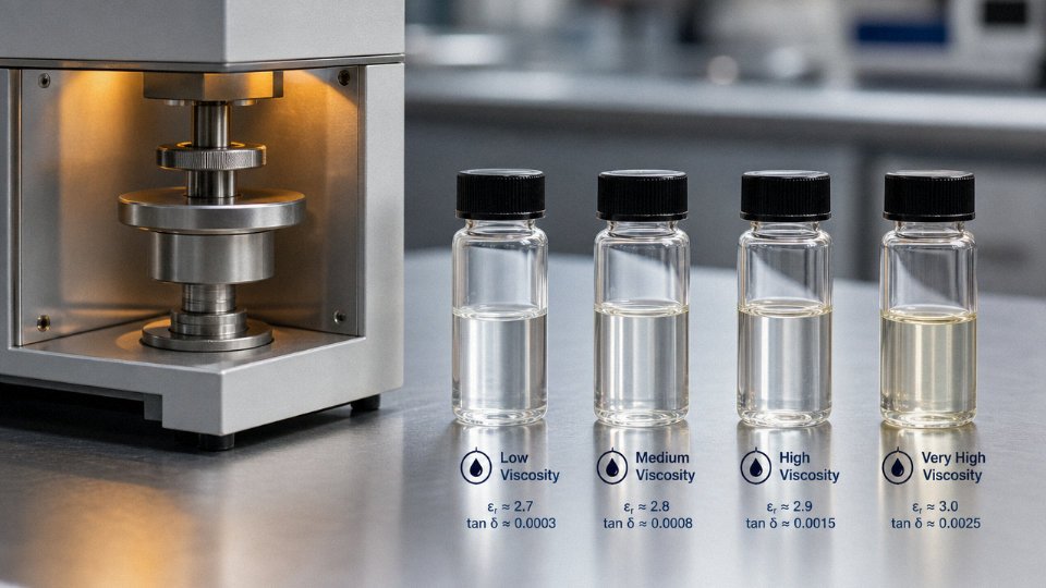
PDMS fluids sit at εr ≈ 2.6–2.8 at 1 MHz, depending on chain length and any phenyl substitution. That sounds narrow, but in RF transmission line cooling applications — where the fluid fills cavities directly adjacent to or around the conductor — even a 0.1 shift in εr changes the effective dielectric constant of the assembly and moves the resonant frequency. For a designer tuning a 2.4 GHz or 5 GHz cavity-cooled amplifier stage, that is not a small error. Phenyl-modified silicones can push εr above 3.0, which in some thermal management datasheets barely gets a footnote. At RF frequencies it needs to be a primary selection criterion, not an afterthought.
Dissipation Factor: Moisture Is the Enemy
Tan δ below 1×10⁻⁴ is the accepted floor for transformer-grade silicone fluid at rated temperature. Fresh, dry, properly synthesized PDMS easily clears this. The problem is water. At 50 ppm dissolved water content — which sounds trivially small and is genuinely easy to accumulate during drum storage, improper filling procedures, or even a humid summer morning with an open fill port — tan δ can jump by an order of magnitude. That pushes dielectric losses into ranges that cause measurable heating in high-frequency transformer cores. The fix is not complicated, but it requires discipline: sealed storage, desiccant-dried handling equipment, and moisture testing before filling, not after.
Moisture contamination at 50 ppm water content can raise dissipation factor by an order of magnitude in PDMS-based silicone fluidsTrue
Water dissolves ionically active species and disrupts the non-polar PDMS matrix, dramatically increasing conduction currents at AC fields; this is well-documented in IEC transformer fluid testing literature and consistent with supplier technical data for electronics-grade PDMS.
Volume Resistivity and Ionic Contamination
Target volume resistivity above 1×10¹⁴ Ω·cm for any genuine insulating application. Premium-grade PDMS fluids from reputable synthesis routes come in at 1×10¹⁵ Ω·cm or higher. The degradation pathway that catches plants off guard is ionic contamination — specifically trace HCl left over from incomplete hydrolysis during manufacturing. Even low-ppm chloride levels create mobile charge carriers, and resistivity can fall an order of magnitude or more over months of service at elevated temperature. This is not hypothetical; it is a known failure mode in potted inverter modules where the fluid was borderline-grade and the junction temperature ran high. Ask your supplier for synthesis route documentation and chloride ion content, not just a resistivity number on the datasheet.
Corona Inception and Partial Discharge: The Metrics That Matter for GIS and Aerospace
For gas-insulated switchgear and aerospace inverter designs, bulk dielectric strength is almost beside the point compared to corona inception voltage (CIV) and partial discharge extinction voltage (PDEV). Corona develops at field concentrations — electrode edges, micro-voids, contamination particles — well below bulk breakdown voltage. A fluid with excellent bulk dielectric strength but poor gas absorption characteristics can actually accelerate partial discharge by releasing dissolved gas under field stress. Silicone oils have relatively high gas solubility compared to mineral oil, which is an advantage here, but it depends heavily on fluid grade and degassing procedure during fill. Specify CIV and PDEV testing explicitly in your procurement documents. For GIS applications or any enclosed high-voltage assembly where you cannot tolerate surface tracking, a minimum PDEV above the operating voltage with a 1.5× margin is a reasonable starting floor.
Procurement Reality Check
Always request IEC 60156 and ASTM D877 test reports with the actual batch number and test date — not the generic product datasheet values, which often represent best-case results from controlled laboratory samples. Specify re-testing after six months of storage, especially for bulk drum inventory sitting in a warehouse through temperature swings. A drum that was compliant at intake can fail resistivity and tan δ specs by the time it reaches the production floor if storage conditions were not controlled. That one extra test, at roughly a few hundred dollars, is cheap compared to a field failure in a 110 kV instrument transformer.
Thermal Management Performance: Conductivity, Heat Capacity, and Immersion Cooling Trade-offs
Silicone oil is not a high-performance thermal fluid. That needs saying plainly, because a lot of immersion cooling marketing glosses over it. Thermal conductivity for PDMS-based fluids runs around 0.15–0.16 W/(m·K) at 25°C — roughly 2.5× lower than water at 0.60 W/(m·K), and actually worse than many engineered fluorocarbons on a per-unit-conductivity basis. Novec-type fluorocarbons sit around 0.065 W/(m·K), so silicone does beat those. The point is that you are choosing silicone oil for its electrical properties, chemical stability, and temperature range, not because it is thermally exceptional. Size your system accordingly.
What Low Conductivity Means for Heat Exchanger Sizing
Lower conductivity forces larger heat exchanger surface areas to achieve the same thermal resistance. A rough rule of thumb: if you are replacing a mineral oil system with silicone oil of similar viscosity, you can often use the same hardware with acceptable derating. Swapping water for silicone in a cold-plate design, however, typically requires 3–4× the contact area to compensate — or a significant flow rate increase. In practice, most single-phase immersion cooling tanks for power electronics use external plate heat exchangers sized conservatively, often at 1.5–2× the theoretical minimum, because fouling margins and uneven flow distribution eat into real-world performance fast.
Specific Heat Capacity and Flow Rate Compensation
PDMS fluids carry roughly 1.46 J/(g·K) of specific heat, compared to water at 4.18 J/(g·K). That gap matters enormously for loop sizing. To move the same amount of heat at the same temperature rise, you need about 2.9× the mass flow rate compared to a water loop. In practice that means larger pumps, wider piping, and a bigger reservoir — or you accept a higher ΔT across the loop, which limits how tightly you can hold component junction temperatures. For GPU server clusters in single-phase immersion, this is usually managed by running high-flow centrifugal pumps (positive-displacement pumps tend to shear silicone oils at higher viscosities) and keeping the inlet-to-outlet temperature differential under 8–12°C depending on how thermally sensitive the load is.
Two-Phase Immersion: Boiling Point Engineering and CHF
Two-phase immersion cooling with silicone oil is viable but genuinely tricky. Low-viscosity PDMS fluids (0.65–2 cSt) can be formulated or selected for boiling points in the 56–100°C range, which puts you in a usable nucleate boiling regime for high-flux electronics. The attraction is that latent heat does the heavy lifting, dramatically improving effective heat transfer coefficients — nucleate boiling with silicone fluids can yield surface heat transfer coefficients of roughly 1,000–3,000 W/(m²·K) depending on surface finish and fluid purity, compared to 200–600 W/(m²·K) in single-phase forced convection.
Critical heat flux is the hard limit. Exceed it and the vapor blanket suppresses boiling, thermal resistance spikes, and you get rapid component overtemperature. For GPU-class heat fluxes (often 30–80 W/cm²), you need to verify CHF margins with the specific fluid and surface geometry — published datasheet values for silicone oils are sparse, and in my experience vendors are slow to provide CHF curves. Budget for testing.
Two-phase immersion cooling with silicone oil achieves higher effective heat transfer than single-phase water cooling in electronics applicationsFalse
While two-phase boiling improves on single-phase silicone oil performance, water's higher thermal conductivity and specific heat capacity mean a well-designed water cooling loop still typically outperforms two-phase silicone immersion on raw heat transfer coefficient unless surface geometry and flux density specifically favor nucleate boiling regimes.
Cold-Start Pumpability and Outdoor Telecom Applications
Pour point for electronics-grade silicone oils typically falls below −50°C. Mineral oil, by comparison, usually gels somewhere between −10°C and −25°C depending on grade. For outdoor telecom cabinets in northern Canada, Scandinavia, or high-altitude installations, that difference is not academic — a mineral oil system on a cold January morning may simply refuse to circulate until the pump has been running for 20–30 minutes and self-heating brings fluid viscosity down. Silicone oil flows from the moment the pump starts, which matters for equipment that needs to be operational immediately after power restoration following an outage.
TIM Gap-Fill: High-Viscosity Silicone as a Reworkable Interface
One underused application is using 50,000–100,000 cSt silicone fluid as a compliant thermal interface between IGBT modules and heat sinks. It does not cure, which means it is reworkable — pull the module, wipe it down, reinstall. Compared to thermal pads, properly applied high-viscosity silicone fluid fills micro-gaps reliably, especially on surfaces with flatness deviations above 50 µm (common on cast aluminum heat sinks that have seen thermal cycling). Thermal resistance values achievable are roughly 0.05–0.15 cm²·K/W depending on bond line thickness and surface quality. The downside is migration under vibration over time; secure the module mechanically and do not rely on the fluid alone to hold position.
Worked Sizing: 500 W Dissipation with 5 cSt Silicone Oil
To dissipate 500 W from a submerged power module with a maximum allowable fluid temperature rise of 30°C, start with the basic sensible heat equation: Q = ṁ × Cp × ΔT. Rearranging: ṁ = Q / (Cp × ΔT) = 500 W / (1,460 J/(kg·K) × 30 K) ≈ 0.0114 kg/s, or roughly 11.4 g/s. At a typical 5 cSt silicone oil density of about 0.91 g/cm³, that converts to approximately 12.5 mL/s, or 0.75 L/min. A small gear pump handles this easily. Where engineers usually undersize is the heat exchanger — budget a surface area that accounts for the low conductivity of silicone, not just the flow rate, and add at least 25–30% margin for real-world flow maldistribution.
Material Compatibility: Plastics, Elastomers, Metals, and PCB Surfaces
Silicone oil’s reputation for chemical inertness is largely deserved — but “largely” is doing real work in that sentence. Get the compatibility screening wrong and you’re looking at swollen seals, stress-cracked housings, delaminated conformal coatings, or creeping contact resistance at edge connectors. None of those failures announce themselves quickly. They tend to show up six months into field deployment, which is exactly when they’re most expensive to fix.
Elastomer Compatibility
PTFE, Viton (FKM), and silicone rubber itself are generally safe choices for static and dynamic seals in silicone oil service. The trouble starts with EPDM and nitrile (NBR), which are still common in off-the-shelf O-rings and gaskets sourced from general industrial suppliers rather than fluid-specific catalogs.
Typical volume swell at 100°C over 168 hours in PDMS fluid:
| Elastomer | Volume Swell (%) | Practical consequence |
|---|---|---|
| PTFE | < 1% | Negligible dimensional change |
| Silicone rubber (VMQ) | 2–5% | Monitor in tight clearances |
| Viton (FKM) | 3–7% | Acceptable for most static seals |
| EPDM | 15–40% | Seal extrusion risk; avoid |
| Nitrile (NBR) | 20–55% | Essentially incompatible |
Swell percentages depend on oil viscosity grade and whether phenyl or amino functional groups are present — methyl-terminated PDMS is the mildest. If you’re using a phenyl-modified fluid at elevated temperature, push those NBR numbers toward the high end.
Thermoplastic Housing and Structural Parts
Polycarbonate is the one that catches engineers off guard most often. PC looks fine on day one. Low-viscosity silicone oil (under roughly 50 cSt) penetrates micro-stress sites — injection molding residual stress, snap-fit flex points, threaded boss areas — and accelerates environmental stress cracking within weeks. Certain ABS grades behave similarly, particularly rubber-toughened formulations where the dispersed phase provides pathways for fluid ingress.
Safe thermoplastics for silicone oil contact: PEEK, PPS (Ryton and equivalents), PA66 (unfilled and glass-filled), and PBT. These show negligible mass uptake and no cracking tendency across the operating range most electronics assemblies see.
Polycarbonate is generally compatible with silicone oil at any viscosity grade.False
Low-viscosity PDMS fluids can penetrate residual stress sites in polycarbonate and trigger environmental stress cracking, even at room temperature over extended contact. PEEK or PPS are the correct substitutes where structural integrity matters.
Metal and PCB Surface Interactions
Aluminum, copper, and stainless steel are inert to standard PDMS under normal operating conditions. That holds up to around 150–180°C without issue. Above 200°C with phenyl-modified fluids, you can see mild oxidative staining on bare copper — cosmetically unpleasant and potentially a concern if it occurs on exposed contact surfaces or fine-pitch lead frames. It’s not dramatic corrosion, but it’s worth knowing.
PCB surfaces present a different problem entirely: capillary wicking. Silicone oil, especially at viscosities below 100 cSt, will migrate under component packages via capillary action along solder mask edges, component stand-offs, and fine-pitch connector interfaces. It displaces flux residues, and those residues — even nominally “no-clean” — can concentrate at contact points and raise contact resistance measurably. Edge connectors are particularly vulnerable. If you’re designing a board that will sit in an immersion-cooled enclosure, specify a solder mask with high surface energy and plan for post-assembly cleaning before immersion.
Conformal Coating Adhesion Failure
This is arguably the most underappreciated compatibility issue in the whole category. Silicone oil vapor, even at sub-monolayer surface coverage, effectively poisons adhesion for acrylic and urethane conformal coatings. The silicone migrates to the lowest-energy surface it can find, which is always the air–substrate interface where you’re trying to form a coating bond.
Prevention protocol, in practice: handle any silicone-oil-wetted components in a physically separated area from conformal coating operations; store boards in sealed packaging if there’s any oil vapor present; degrease with isopropyl alcohol plus a short ultrasonic cycle before coating; and run an adhesion pull test on witness coupons from each batch rather than trusting process records alone.

Structured Compatibility Test Protocol
Don’t rely solely on published compatibility tables — they’re often generated at different temperatures, durations, or fluid grades than your actual application. Run your own coupon immersion test before committing to a design.
Test conditions: Immerse cut coupons (roughly 25 × 25 × 3 mm) in the specific oil grade you intend to use, at your maximum expected service temperature, for a minimum of 168 hours (one week). Use a fluid-to-specimen volume ratio of at least 10:1 to avoid depletion effects.
Acceptance criteria:
– Mass change: ≤ 5% for elastomers, ≤ 1% for thermoplastics
– Linear dimensional change: ≤ 2% in any axis
– Tensile strength retention: ≥ 80% of baseline for elastomers
If a candidate material fails any criterion at 168 hours, it fails. No appeals. Real field life is longer and conditions are less controlled than your lab setup.
Purity Standards and Contamination Control for Semiconductor and Precision Electronics Environments
Viscosity and dielectric strength get most of the attention in silicone oil selection, but in semiconductor fabrication, MEMS packaging, and optical subassembly work, the contamination spec is what actually kills yield. A fluid that looks perfectly clean to the naked eye can carry enough ionic load or cyclic siloxane vapor to degrade a wire bond or fog an optical surface over weeks. The damage is slow, insidious, and by the time it shows up in field returns, the root cause is hard to pin down.
Ionic Purity: The Numbers That Matter
Electronics-grade silicone oil should come with documented ionic analysis — specifically sodium, potassium, and chloride — held below 1 ppm each, with total ionic content similarly sub-ppm. Industrial-grade PDMS fluids, even from reputable suppliers, routinely run 10–50 ppm ionic load. That range sounds abstract until you consider that Na⁺ and Cl⁻ ions in a closed-loop immersion cooling system will migrate under electric field gradients and deposit on die surfaces. On bare silicon, ionic contamination accelerates surface leakage currents and can shift MOSFET threshold voltages measurably over time — months, not years.
Electronics-grade silicone oils should have Na, K, and Cl each below 1 ppm to avoid ionic contamination failures in semiconductor environments.True
This threshold is consistent with semiconductor-grade chemical specifications and is driven by the sensitivity of bare silicon die and wire bonds to ionic deposition under operating electric fields.
Request the full ionic analysis in the certificate of conformance, not just a pass/fail statement. If a supplier can’t provide batch-level ICP-MS data, that’s a straightforward disqualification for any wafer-level or die-level application.
Particulate Cleanliness Grades
For closed-loop cooling circuits that pass fluid over bare die or exposed bond wires, ISO 4406 cleanliness at Class 12/10/7 or better is the practical floor — and some MEMS packaging lines demand tighter. A particle landing on a 25 µm bond wire isn’t necessarily catastrophic immediately, but it creates a nucleation site for contamination buildup and can abrade gold or aluminum wire under vibration. Filtration at point of use (typically 0.2 µm or 0.45 µm membrane filters) is standard practice, but that doesn’t substitute for specifying a clean incoming fluid. Starting with a heavily particulate-laden industrial fluid and trying to filter it down in-house is slower, more expensive, and risks membrane breakthrough during high-flow events.
Cyclic Siloxane Migration: The Hidden Optical and Bond-Wire Problem
D4, D5, and D6 cyclic siloxanes are low-molecular-weight volatiles present in most standard PDMS fluids as process residuals. At room temperature they’re not immediately obvious, but in any enclosed enclosure — optical sensor housings, camera modules, hermetic packages — they migrate, condense on cooler surfaces, and polymerize under UV or heat into a thin, glassy silicone film. On an optical lens this means haze. On a gold bond wire it means increased contact resistance, sometimes climbing from milliohm to tens-of-milliohm range depending on exposure duration and temperature cycling.
Low-cyclic grades specify D4+D5+D6 combined below 0.1% by mass, occasionally below 0.05% for the most sensitive optoelectronic applications. Verify this with GC-MS data, not just a supplier’s product description. In practice, the cyclic content can vary batch to batch if the manufacturer’s stripping process isn’t tightly controlled, so incoming QC on every lot matters here.
Outgassing: TML and CVCM for Space and High-Reliability Electronics
For space electronics and any application involving sensitive detector arrays or hermetically sealed cavities, outgassing behavior is specified via ASTM E595 testing: total mass loss (TML) must stay below 1.0% and collected volatile condensable materials (CVCM) below 0.1%. Most well-specified electronics-grade silicone oils pass comfortably — TML often running 0.1–0.3%, CVCM well under 0.05% — but this depends heavily on the specific formulation and any additives. Antioxidants, viscosity modifiers, and adhesion promoters all contribute to the outgassing profile. A base PDMS fluid might pass easily; the same fluid with a pour-point depressant additive might not.
Storage, Handling, and Incoming QC
Contamination introduced after leaving the supplier is just as damaging as contamination in the original fluid. Standard practice for semiconductor-adjacent applications means dedicated stainless steel dispensing equipment (never shared with mineral oil or hydraulic fluid lines), nitrogen blanket storage to prevent moisture absorption and oxidation, and strict shelf-life adherence — typically 24 months sealed, less once opened. Drums that sat in an uncontrolled warehouse for 18 months before use are a real-world source of otherwise unexplained yield excursions.
A practical incoming QC checklist should include: batch-level certificate of conformance with ionic analysis, viscosity verification against spec, GC-MS cyclic content confirmation, ISO 4406 particle count on a sample pulled at receiving, and ASTM E595 data from either the supplier or a third-party lab for space-grade work. For aerospace and medical supply chains, also require full batch traceability back to raw material lots and a documented change notification procedure — so that if the supplier reformulates even subtly, you find out before it reaches your process.
Supplier qualification isn’t a one-time event. Annual audits and periodic third-party analytical verification catch the slow drift in process quality that happens when a supplier deprioritizes a low-volume specialty grade. In my experience, the most common failure mode here isn’t outright fraud — it’s gradual quality erosion that nobody notices until a reliability excursion forces a root-cause investigation.
Regulatory Compliance and Environmental Considerations: REACH, RoHS, and Sustainability
If you’re specifying silicone oils for a product sold into the EU, US, or California markets, compliance isn’t a box to check at the end of the design cycle. Regulatory status can eliminate a fluid candidate entirely, or at minimum force a disclosure chain that procurement teams aren’t always prepared to manage.
REACH SVHC Status of Cyclic Siloxanes D4 and D5
D4 (decamethylcyclopentasiloxane) and D5 (dodecamethylcyclohexasiloxane) are listed under REACH Annex XIV — the Authorization List — meaning their use in the EU requires explicit authorization or must fall within a granted exemption. Both are classified as persistent, bioaccumulative, and toxic (PBT) substances. In practice, most electronics-grade silicone oils are linear PDMS or phenyl-modified fluids, not cyclic siloxanes, but trace D4/D5 can appear as synthesis byproducts in lower-purity grades. Your supplier’s Safety Data Sheet won’t always flag this unless you explicitly request a cyclic siloxane content certificate.
For supply chain disclosure: any article or mixture containing an SVHC above 0.1% w/w triggers the REACH Article 33 obligation to inform customers and, on request, consumers within 45 days. If you’re a contract electronics manufacturer shipping finished assemblies into Europe, that obligation lands on you even if the silicone oil is buried inside a sealed thermal interface or immersion bath.
D4 and D5 cyclic siloxanes are listed under REACH Annex XIV and require EU authorization for use above threshold concentrationsTrue
Both D4 and D5 appear on the REACH Annex XIV Authorization List due to PBT classification under EU Regulation No 1907/2006, with sunset dates that have passed, meaning ongoing use requires granted authorization or confirmed exemption.
RoHS and Halogenated Residuals
Silicone oils as a class are not RoHS-restricted substances — there’s no RoHS line item that targets PDMS directly. The risk surfaces with chlorosilane-derived manufacturing residuals. Chlorosilanes are standard precursors in PDMS synthesis, and incomplete purification can leave chlorine-containing species in the finished fluid. RoHS Annex II doesn’t restrict chlorine per se, but if a halogenated silicone variant is present in concentrations that read as chlorinated compounds during XRF screening, you can get a false positive that stalls customs clearance or triggers a customer nonconformance. Request a certificate of analysis showing Cl content below 900 ppm (the RoHS threshold applies to homogeneous materials, so context matters, but 900 ppm is the practical working limit most compliance teams use).
EPA and Proposition 65 Exposure Considerations
For US facilities, silicone oils don’t currently appear on the EPA’s Toxics Release Inventory at typical use concentrations, but phenyl-modified grades carry aromatic content that warrants a closer look under Proposition 65 if your California facility handles quantities above the threshold for workplace air monitoring. Biphenyl and certain polycyclic aromatics can be present depending on the phenyl silicone synthesis route. This isn’t common, but it’s not hypothetical either — check the phenyl content specification and request aromatic speciation data from the supplier if you’re operating a large immersion cooling tank in a California facility.
Biodegradability and Environmental Fate
Linear PDMS degrades in soil primarily through hydrolysis catalyzed by clay minerals, breaking down to silica, CO₂, and water. The half-life ranges from roughly a few months in fine-textured soils with high clay content to several years in sandy or low-organic soils — particle size of the silicone droplets matters significantly, as does soil moisture. This degradation pathway is generally considered benign, and documenting it for facility environmental permits is straightforward: most jurisdictions accept the published OECD 308 sediment simulation data that suppliers can provide. For ISO 14001-registered facilities, include the fluid’s environmental fate profile in your chemical register and link it to your spill response procedure.
Sustainability Alternatives and End-of-Life Management
Bio-derived silicone precursors — using bioethanol or plant-derived silicon feedstocks — are under active development, but as of now most are at technology readiness level 4–6. Performance gaps versus conventional PDMS remain real: viscosity-temperature behavior and dielectric strength are generally comparable in lab samples, but long-term oxidative stability data in electronics environments is thin. Low-GWP immersion cooling fluids (certain hydrofluoroethers and synthetic esters) offer partial alternatives for single-phase immersion, though they carry their own compatibility constraints with elastomers and some plastics.
For end-of-life, spent silicone oil from large immersion cooling systems or transformer baths should go to a certified silicone reclaimer rather than general solvent waste streams — several processors in North America and Western Europe re-refine PDMS fluids back to usable viscosity grades, which is both cheaper than virgin fluid and documentable under ISO 14001 waste reduction metrics. Keep the batch records and the waste transfer documentation; auditors increasingly ask for chain-of-custody on specialty fluids. Don’t mix silicone waste with mineral oil or synthetic ester streams — it contaminates both and eliminates the reclaim option.
Supplier Evaluation and Total Cost of Ownership Beyond the Price-per-Liter
Unit price is the wrong variable to optimize. A procurement team that selects a silicone oil supplier on price-per-liter alone will, reliably, generate downstream costs that dwarf any savings on the purchase order — rework labor, system flushing, re-qualification engineering time, and in the worst cases, field failures that trace back to a fluid that was mislabeled or inconsistently manufactured.
Tier-1 vs. Tier-2 Supplier Risk and Second-Source Strategy
For commodity viscosity grades — 50 cSt or 100 cSt PDMS with no special ionic purity requirements — the supply market is deep enough that single-source dependency is manageable. Specialty grades are a different problem. Low-cyclic phenyl silicone fluids, ultra-high-purity immersion cooling grades, and anything with a specified cyclic siloxane content below 100 ppm exist in a much thinner market. A single production line shutdown at the primary supplier — planned or not — can leave you with a 12–20 week lead time gap and no approved alternative.
The correct approach is to qualify a second source during the project development phase, not during a supply crisis. That said, re-qualification for electronics applications typically means running a full compatibility screen, repeat dielectric measurements, and sometimes accelerated aging tests on assemblies. Budget 8–16 weeks and real engineering hours for this. One practical shortcut: identify second-source candidates whose product is synthesized via the same polymerization chemistry and ask both suppliers for GC-MS cyclic siloxane profiles. If the profiles are comparable, you can sometimes support an abbreviated qualification to your customer or internal approval body. This is not universal — it depends entirely on your end application’s criticality and whether your quality system allows equivalence arguments — but it has worked in practice for non-critical conformal coating carrier fluids.
Batch-to-Batch Consistency: Where Mislabeled Fluid Does Real Damage
Acceptable viscosity tolerance for electronics-grade silicone oil is generally ±5% of the nominal value at 25°C. That’s an industry-understood standard, and reputable manufacturers hold it without difficulty. The problem is that some distributors and second-tier producers ship fluid with ±15% tolerance — a specification appropriate for general industrial or mold-release applications — with labeling that implies electronics suitability. At 100 cSt nominal, ±15% means you might receive fluid anywhere from 85 to 115 cSt. For a transformer cooling circuit or an immersion-cooled server rack, that swing affects flow resistance, heat transfer coefficient, and pump sizing assumptions. The failure mode is usually gradual — slightly higher operating temperatures, shortened component life — rather than immediate, which makes it hard to trace back to the fluid without lot-level viscosity records.
Electronics-grade silicone oils require batch-to-batch viscosity consistency within ±5% of nominal; broader tolerances indicate industrial-grade fluid regardless of labeling.True
Major manufacturers including Shin-Etsu, Dow, and Wacker specify ±5% viscosity tolerance on their electronics-grade certificates of analysis. Industrial grades routinely carry ±10–15% tolerances, and mislabeling has been documented in distribution channels where product is repackaged or relabeled outside the original manufacturer's quality system.
Technical Data Package: What You Should Demand Before Approving Any Supplier
A lot-specific Certificate of Analysis (CoA) is non-negotiable. Not a generic product datasheet — an actual lot-level document with measured values for viscosity, refractive index, and (for high-purity grades) ionic contamination and cyclic siloxane content, traceable to the synthesis batch number. GHS-format SDS is a baseline compliance requirement, not a differentiator. Beyond those, ask specifically for:
- Third-party analytical confirmation for cyclic siloxane content (D3, D4, D5, D6 species) if the application involves semiconductor or MEMS environments
- Shelf life data and storage condition specifications — silicone oils are stable, but contamination during storage is a real mechanism
- Application engineering contact with demonstrated electronics experience, not just a general technical hotline
If a supplier cannot produce lot-traceable documentation within 48 hours of request, that tells you something operational about their quality system.
Global Manufacturers Worth Knowing
The short list of manufacturers whose electronics-grade lines appear consistently in serious procurement conversations: Dow’s Xiameter and Syltherm product lines are widely available globally and have deep technical documentation. Shin-Etsu’s KF series covers an enormous viscosity range with strong lot consistency and is particularly well-represented in Asian supply chains. Momentive’s Clearco and TSF series have long histories in high-voltage and transformer applications. Wacker’s AK series is well-regarded in European manufacturing and available in electronics-appropriate purity tiers. Elkem serves some specialty and regional markets. All five have application engineering teams capable of supporting qualification — a practical asset when your engineering team is writing the first version of a compatibility protocol.
Building the Actual TCO Model
The math is straightforward once you list all the components. Fluid unit cost is usually 15–35% of true lifecycle cost for specialty grades, depending on the application. The remaining cost is: system flush and refill labor (which in a sealed immersion cooling system can run several person-days plus the cost of flush fluid), downtime risk premium if supply disruption forces an emergency re-source, disposal cost (silicone fluids are not hazardous but do require proper collection and processing, typically $2–6 per liter depending on region and volume), and re-qualification engineering cost if a supplier changes formulation — which happens, usually with inadequate notice.
The red flags that should halt a supplier approval process: no lot-specific CoA available, refusal to provide third-party cyclic siloxane data for a grade being sold into semiconductor-adjacent applications, pricing 30–40% below the market range for a specialty grade (the chemistry does not support that margin), and inability to confirm what the D4/D5 cyclic siloxane levels actually are in their product. That last point matters increasingly under European REACH restrictions on cyclic siloxanes in consumer and industrial applications. A supplier who cannot answer that question is a supplier whose quality system cannot support an electronics application.
Step-by-Step Selection Decision Framework with Application Matrix
By the time you reach this point in the design process, you should already have a shortlist of chemistry variants, a feel for viscosity range, and some compatibility data. What tends to go wrong is that engineers jump straight to a specific product and skip the structured cross-check. One step out of order — say, confirming chemistry before you’ve locked down the operating voltage class — and you’ll find yourself requalifying fluid mid-prototype.
Step 1 – Application Definition Checklist
Before you open a single datasheet, write down six parameters. Operating voltage class (signal-level, low-voltage up to roughly 1 kV, medium-voltage 1–36 kV, or high-voltage above that). Minimum and maximum operating temperature — not ambient, actual fluid temperature at steady state and at cold start. Heat load in watts, or at least an order-of-magnitude estimate. Fluid containment method (sealed enclosure, open bath, impregnated gap, or flow-through). Every contact material the fluid will touch: connector housing polymer, gasket elastomer, wire insulation, PCB surface finish, and any metal alloys. Regulatory jurisdiction, because a fluid that’s fully compliant under EPA rules may still require REACH pre-notification if it ships through an EU distribution hub.
Skipping any one of these creates ambiguity that costs you later. Temperature range and contact materials together will eliminate maybe 40–60% of candidate fluids before you’ve done a single test.
Step 2 – Primary Function Ranking
Rank the four functions in order of criticality for your design: dielectric isolation, thermal transfer, mechanical damping, and environmental sealing. This ranking determines which property family gates your shortlist.
A high-voltage transformer filling is dielectric-first. An immersion-cooled GPU tray is thermal-first. A gyroscope damping application is viscosity-stability-first, which falls under damping. A conformal coating base might be sealing-first. The ranking matters because some of these functions pull viscosity in opposite directions — good dielectric fluids often sit in the 10–100 cSt range, while damping applications may need 1,000 cSt or above — and you need to know which constraint wins when they conflict.
Step 3 – Viscosity Grade Pre-Selection Matrix
| Application | Viscosity Range (cSt at 25°C) | Min Dielectric Strength | Max Continuous Temp | Purity Grade |
|---|---|---|---|---|
| Transformer filling | 10–100 | ≥15 kV/mm | +150 to +180°C | Electronics-grade, low ionic |
| Immersion cooling | 1–10 | ≥14 kV/mm | +180 to +200°C | Ultra-low particulate |
| Damping / gyro | 500–100,000+ | Not primary | +100 to +150°C | Standard electronics |
| Conformal base fluid | 50–350 | ≥12 kV/mm | +150°C | Low-cyclic PDMS preferred |
| Potting / encapsulation | 1,000–30,000 | ≥15 kV/mm | +200°C | Low-cyclic, low-extractable |
Figures depend heavily on enclosure design, fluid volume, and whether the system sees continuous or intermittent thermal cycling. Treat these as starting corridors, not absolutes.
Step 4 – Chemistry Variant Selection
General-purpose PDMS covers most applications below roughly 150°C continuous. Phenyl-modified grades are worth the cost premium when you’re above 180°C steady state or in a radiation-exposed environment — the phenyl groups genuinely improve thermal oxidative stability, not just on paper. Fluorosilicone is the right call if the fluid contacts hydrocarbon fuels, aggressive solvents, or lubricating oils, even occasionally. Low-cyclic PDMS grades (D4/D5 content tightly controlled) belong anywhere near open semiconductor wafer processes or precision optical assemblies.
Phenyl-modified silicone oils maintain dielectric strength better than standard PDMS at sustained temperatures above 180°C.True
The phenyl side groups reduce oxidative chain scission at elevated temperature, preserving fluid integrity and dielectric properties over longer service intervals compared to dimethyl-only PDMS.
Step 5 – Compatibility Screening
Run coupon tests. Cut samples of every contact material — all of them, not just the ones you’re uncertain about — immerse them in your candidate fluid, and hold at the maximum operating temperature for at least 168 hours. Weigh and dimension before and after. Anything showing more than roughly 2–3% mass change or visible surface degradation is a disqualifier. In practice, silicone fluid with a polycarbonate housing is a common failure waiting to happen; the visual clarity test on the fluid after extraction tells you if the polymer is leaching plasticizer.
Don’t shortcut to 72 hours because the schedule is tight. The difference between 72 and 168 hours shows up on the production line six months later as swollen seals and cloudy fluid.
Step 6 – Supplier Qualification and Incoming Inspection
On every received lot: viscosity spot-check against the certificate of analysis (a Cannon-Fenske tube and a temperature-controlled bath is sufficient for incoming QC), visual clarity check against a white background in daylight, and Karl Fischer titration for water content — target below 50 ppm for most electronics-grade applications, below 20 ppm for anything near high-voltage gaps. Dielectric strength verification on a sample from each drum is non-negotiable if the fluid is going into insulation service; a Baur or similar oil tester takes under 10 minutes per sample.
Keep a retained sample from each lot. If a field failure surfaces eight months later, you want to know whether the fluid met spec at receipt or whether something happened in storage.
Frequently Asked Questions About Silicone Oil for Electronics

Can I use food-grade or cosmetic silicone oil in an electronic assembly?
Short answer: don’t. Cosmetic and food-grade PDMS fluids are formulated for skin safety and inertness toward food packaging — not for electrical performance. They’re not tested for dielectric strength, they carry no guarantee on ionic impurity levels, and cyclic siloxane content (D4, D5, D6) is often uncontrolled. In a high-voltage application, that untested ionic load can create leakage paths that didn’t exist on day one but develop over a few hundred operating hours. Always specify electronics-grade fluid and require a full Certificate of Analysis showing dielectric strength, viscosity, and — where it matters — ionic contamination levels. The price difference between cosmetic-grade and electronics-grade is usually small enough that trying to save money here is a false economy.
Food-grade and cosmetic silicone oils are equivalent to electronics-grade silicone oils for dielectric applications.False
Food-grade and cosmetic silicone oils are not tested for dielectric strength, ionic purity, or cyclic siloxane content. Electronics-grade fluids require controlled purity and full CoA documentation to meet electrical performance and reliability requirements.
How do I remove silicone oil contamination from a PCB?
This is more stubborn than most technicians expect. Standard flux cleaners and water-based defluxers have almost no effect on PDMS — the fluid just redistributes. What actually works is ultrasonic cleaning with a low-residue IPA-based cleaner or a dedicated silicone degreaser; Electro-Wash PX is one commonly stocked option in electronics rework shops. Follow that with a DI water rinse to clear any ionic residue left by the solvent. For heavy contamination, two cleaning passes are often necessary. Bake the board dry before any electrical test — silicone oil’s tendency to trap moisture under components is the part people forget, and a damp board will give you misleading continuity readings.
Does silicone oil degrade in service, and how should I monitor it?
PDMS is genuinely stable at moderate temperatures, but above roughly 150°C sustained operation, slow oxidative degradation does occur, and it accelerates with contamination or moisture ingress. The practical monitoring protocol: check viscosity periodically (the interval depends on operating temperature and fill volume — quarterly is reasonable for a continuously energized transformer, annually may be fine for a sealed relay enclosure). A viscosity drift greater than about 10% from the original grade is a reasonable trigger for investigation or replacement. Dielectric strength testing per IEC 60156 and acid number titration round out the picture. Acid number rising above roughly 0.1 mg KOH/g usually indicates meaningful oxidation is underway.
What is the difference between silicone oil and silicone grease for thermal interface use?
Silicone grease is silicone oil loaded with thermally conductive filler — typically Al₂O₃, ZnO, or hexagonal BN — to push thermal conductivity into the 1–4 W/(m·K) range depending on filler loading. Pure silicone oil has no filler, thermal conductivity sits around 0.15–0.16 W/(m·K), and you’d use it where the fluid needs to flow into irregular gaps, where reworkability matters, or in immersion cooling where bulk convection is doing the real work anyway. They are not interchangeable. Using unfilled silicone oil as a thermal interface material on a high-power device is a real mistake that shows up occasionally in prototypes built by people who grabbed what was available.
Is silicone oil flammable?
PDMS fluids have open-cup flash points typically above 300°C, which puts them well above mineral oil (roughly 150°C) and makes them much safer to store and handle in most plant environments. That said, fine aerosol mists of low-viscosity grades — say, below 5 cSt — can ignite under the right conditions. Don’t use spray application near open flames or hot work. For most sealed electronic applications the flammability risk is genuinely low, but the mist hazard is worth briefing anyone doing maintenance top-ups.
Can I mix silicone oils from different suppliers or grades?
PDMS fluids of the same base chemistry are generally miscible without phase separation. Mixing grades of the same type — say, two straight PDMS fluids at different viscosities — typically produces a predictable blended viscosity. Where it gets unpredictable is mixing chemically distinct variants: blending a phenyl-modified fluid with a standard PDMS can shift dielectric constant, viscosity-temperature behavior, and low-temperature pour point in ways that aren’t obvious from the individual datasheets. If you’re considering any blend, confirm compatibility with at least one of the suppliers before committing a production batch to it.
What viscosity silicone oil is best for single-phase immersion cooling of servers?
The industry has largely converged on 3–10 cSt measured at actual operating temperature for single-phase immersion systems. In practice, 5 cSt at 40°C is the most widely validated starting point — it balances pump energy consumption, heat transfer coefficient at the board surface, and an acceptable evaporative loss rate from the bath. Going lower than 3 cSt reduces pumping losses but increases evaporation and can cause oil migration into connectors at tank entry points. Going above 10 cSt improves that, but you start paying more in pump energy and the heat transfer at low-flow areas of a densely packed chassis becomes noticeably worse. The right answer shifts slightly depending on your specific server layout and whether you’re running a pumped or purely convective system.