Poor silane application is one of those process failures that hides until it’s too late. Adhesion fails at the bonding interface, rubber compounds delaminate mid-run, glass fiber reinforcements pull out at frustratingly low loads — and the root cause traces back not to the silane chemistry itself, but to how it was prepared and deposited. Scrap rates climb, warranty claims stack up, and the cost of rework in a filled-compound or composite line can dwarf the price of the coupling agent by an order of magnitude.
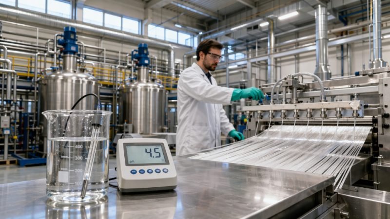
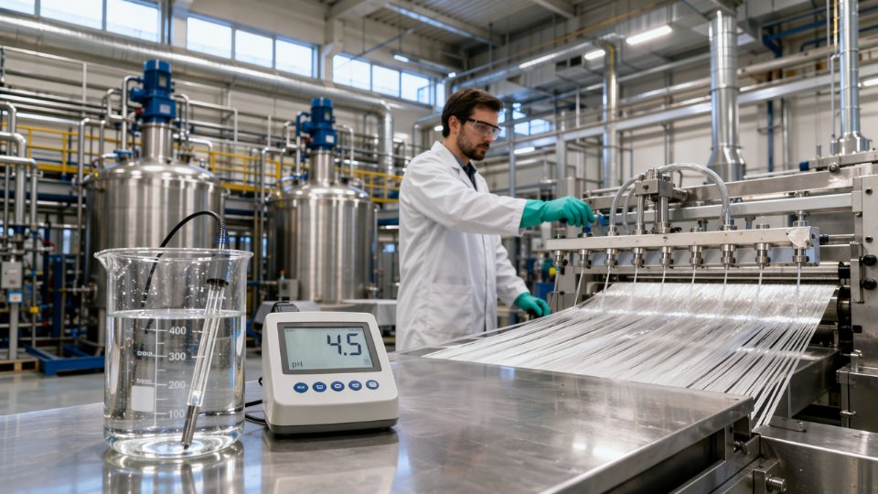
To apply a silane coupling agent correctly, prepare a 0.5–2.0 wt% aqueous hydrolysis solution at pH 3.5–5.5 (aminosilanes) or 4.0–5.0 (vinyl- and epoxysilanes) using dilute acetic acid or a citric acid buffer, allow 15–30 minutes of hydrolysis time, apply uniformly to the substrate surface, then dry and cure at 110–150 °C for 10–30 minutes depending on substrate mass and silane chemistry.
What makes this deceptively difficult is that each variable — concentration, pH, contact time, cure temperature — interacts with the others in ways that don’t show up in a spec sheet. Get one wrong and the silane either never fully hydrolyzes, deposits as a thick oligomeric film that weakens rather than strengthens the interface, or cures before it has bonded to the substrate. The sections below work through each stage of the process the way a process engineer would: with the failure modes front and center.
Selecting the Right Silane Grade Before You Touch the Equipment
The single most expensive silane application mistake happens before any mixing bowl turns or spray nozzle opens: specifying the wrong functional group for your polymer matrix or substrate. A technically perfect hydrolysis procedure applied with the wrong silane chemistry produces bonding strength indistinguishable from an untreated surface. Grade selection is not a catalog exercise — it requires matching three variables simultaneously: the organic functional group to the matrix resin’s cure chemistry, the hydrolytic group (methoxy vs. ethoxy) to your VOC and processing constraints, and the purity specification to what your quality system can actually verify.
Functional Group to Matrix Chemistry — The Core Decision
Different resin systems require fundamentally different reactivity at the organic end of the silane molecule. Using a vinylsilane in an epoxy-matrix composite because “it was in stock” is a common floor-level error that shows up weeks later as delamination or moisture-induced failure rather than immediately as a rejected batch.
| Silane Type | Common Grades | Compatible Matrix Chemistry | Mechanism |
|---|---|---|---|
| Aminosilane | KH-550, A-1100 | Epoxy, polyamide, phenolic | Amine reacts with epoxide or acid groups |
| Vinylsilane | KH-151, KH-171 | Peroxide-cured rubber, polyolefins | Free-radical addition during cure |
| Epoxysilane | KH-560, A-187 | Epoxy, polyurethane, acrylate | Ring-opening with amines or hydroxyl groups |
| Methacryloxysilane | KH-570 | UV-cure, radiation-cure resins | Vinyl co-polymerization with acrylate network |
| Mercaptosilane | KH-590 | Sulfur-vulcanized rubber | Thiol participates in sulfur crosslink network |
Mercaptosilanes are a useful reminder that the organic end must be chemically active under your specific cure conditions — not just broadly “reactive.” A mercaptosilane in a peroxide-cured compound contributes essentially nothing to interfacial bonding because there is no sulfur crosslink network for the thiol to enter.
Substrate Hydroxyl Density Changes Your Loading Calculation
Glass fiber and fumed silica carry surface hydroxyl densities in the range of 4–8 OH groups per nm², which means silane molecules have abundant anchor points and relatively low effective loading levels (typically 0.5–1.0 wt% on filler) are sufficient to achieve near-monolayer coverage. Calcium carbonate, talc, and wollastonite present significantly lower hydroxyl density — often below 2 OH/nm² depending on particle morphology and surface history — and respond poorly to standard glass-treatment loading levels. On these substrates you may see no measurable improvement in mechanical properties not because the silane failed to react with the polymer matrix, but because there was insufficient inorganic bonding to anchor the interface. Engineers moving a formulation from glass-filled to talc-filled compound sometimes carry the same silane concentration across unchanged; that shortcut routinely produces disappointing impact and tensile data.
Purity and Hydrolysis Stability — What to Request on the CoA
For production-grade silane, request assay ≥98% by GC analysis, moisture content <0.05 wt%, and clearly stated shelf life under nitrogen blanket storage (typically 12–24 months, shorter for aminosilanes which absorb CO₂ and moisture more aggressively). A certificate of analysis should specify: GC assay with method reference, water content by Karl Fischer titration, refractive index, density, color (APHA), and any chloride content if the product is synthesized via chlorosilane routes. Residual chloride above roughly 50–100 ppm can cause corrosion on metal processing equipment and interfere with pH-sensitive hydrolysis baths — a problem that rarely appears in the supplier’s sales literature.
Aminosilanes with moisture content above 0.1 wt% will show accelerated self-condensation in storage, reducing active monomer concentration before the product even reaches your process line.True
Aminosilane's basic nitrogen catalyzes Si-OH condensation; elevated moisture content accelerates oligomerization in the drum, measurably reducing the concentration of monomeric silane available for substrate bonding.
Methoxy vs. Ethoxy — The VOC Compliance Variable
Methoxysilanes hydrolyze faster than ethoxysilanes, which can be operationally convenient in short dwell-time continuous processes. The byproduct of methoxy hydrolysis is methanol; ethoxy hydrolysis releases ethanol. In facilities operating under solvent emission regulations — particularly under EU VOC directives or certain OSHA PEL thresholds in enclosed mixing environments — methanol generation from methoxysilanes may require local exhaust ventilation upgrades or a formal substitution to ethoxysilane grades. This is a selection criterion that procurement often misses entirely because the regulatory exposure only becomes visible during an environmental compliance audit rather than during initial qualification testing.
Economic Reality for High-Volume Compounders
Neat silane cost per treated kilogram of filler depends on the loading level, silane unit price, and treatment efficiency — not just the drum price. At a typical 0.8 wt% loading on a glass filler running at several hundred kilograms per hour, the silane line item per tonne of compound falls in a range heavily influenced by whether you are purchasing in 25 kg drums versus 200 kg drums versus IBC tote quantities. Bulk and drum supply through an integrated supplier like SiliconChemicals typically reduces unit cost by 15–30% compared to small-pack sourcing, with the lower end of that range for commodity grades like KH-550 and the higher end for specialty grades with tighter purity specifications. The calculation that matters is not silane cost alone but silane cost against the scrap and rework cost of under-performing interface bonding — a failed batch of glass-fiber-reinforced nylon rejected for tensile shortfall costs orders of magnitude more than the incremental cost of correct grade specification.
Aqueous Hydrolysis Method: Step-by-Step Protocol for Filler and Fiber Treatment
Pre-hydrolysis is not a preparatory nicety — it is the mechanism that determines whether silane chemistry actually reaches the substrate surface. In an unhydrolyzed state, the alkoxy groups (-OCH₃ or -OC₂H₅) must react with surface hydroxyl groups while simultaneously competing with bulk condensation between silane molecules. That competition produces oligomeric silane clusters that settle on the filler surface as a thick, poorly bonded layer rather than a covalently grafted monolayer. The practical consequence: inferior coupling efficiency, erratic mechanical properties in the compound, and batch-to-batch variation that is nearly impossible to troubleshoot without understanding why pre-hydrolysis was skipped or done poorly.
Preparing the Hydrolysis Solution Correctly
Start with deionized or softened water. Hard water above roughly 100 ppm calcium carbonate equivalent will interfere with silanol formation by precipitating calcium silicate complexes on the filler — a slow, insidious quality problem that shows up weeks later as inconsistent tensile strength, not immediately as visible contamination.
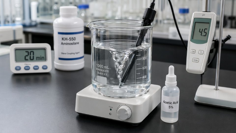
Dissolve the silane into a 95:5 water-to-ethanol mixture by volume. The alcohol serves as a co-solvent that aids initial dispersion of the silane before hydrolysis begins; it evaporates during drying and does not remain in the finished product at meaningful levels. Add dilute acetic acid — a 5–10 wt% stock solution works well for accurate dosing — to bring the bath to pH 4.0–5.0. Aminosilanes tolerate a slightly wider window of 3.5–5.5 because the amine group acts as an internal buffer, but staying closer to 4.5 is safer across silane types. Vinylsilanes and epoxysilanes are less forgiving: drift above pH 5.5 and hydrolysis slows sharply; drift below 3.5 and acid-catalyzed oligomerization accelerates.
Stir continuously and allow 15–30 minutes at room temperature. The solution should go from slightly cloudy to water-clear as silanols form and any initial precipitate redissolves. If it does not clear within 30 minutes, check pH, verify the silane is the correct grade, and confirm water hardness. A persistent haze at correct pH is a reliable indicator that silane has already oligomerized in storage — that batch should not be used.
Concentration by Substrate Type
Target concentrations depend on specific surface area and the add-on level required:
| Substrate | Silane Solution Concentration | Typical Add-On Target (wt% on filler) |
|---|---|---|
| Glass fiber sizing (continuous) | 0.5–1.0 wt% | 0.1–0.3% |
| Precipitated or fumed silica | 1.0–2.0 wt% | 1.5–3.5% |
| Glass fabric (woven, surface treatment) | 0.3–0.8 wt% | 0.05–0.15% |
Add-on percentage is calculated as: (dry weight gain ÷ original substrate weight) × 100. Loss-on-ignition at 950 °C against an untreated control is the standard production-floor method for verifying this — run it on every new batch during process qualification and at a minimum weekly cadence during steady production.
Application Equipment and Contact Parameters
For continuous glass fiber, a spray bar system with controlled nip rollers is standard. Dip-bath impregnation suits woven fabrics; bath concentration and dwell time (typically 5–15 seconds) together control add-on, so changing one without adjusting the other breaks your target. For mineral filler slurries, a high-shear paddle mixer with a tip speed of 3–6 m/s ensures uniform coating without generating excessive foam. Below 3 m/s, agglomerate breakdown is inadequate; above 6 m/s, you introduce air and risk foaming that dilutes effective silane contact.
Drying and Condensation Cure
A staged thermal profile is worth the energy cost. First, hold at 80 °C for 8–12 minutes to drive off free water and ethanol without forcing rapid condensation that can trap residual solvent within the siloxane network. Then ramp to 120–150 °C for 15–20 minutes to complete Si-O-substrate bond formation and cross-link the siloxane layer. Skipping the low-temperature dwell and going straight to 150 °C produces a brittle, cracked silane film — measurable as a poor contact angle and confirmed as low dispersibility in downstream resin mixing.
Staged drying at 80 °C before curing at 120–150 °C produces a more complete and defect-free siloxane network than single-temperature cure at the higher temperature alone.True
Rapid evaporation at high temperature creates vapor pressure that physically disrupts the partially condensed silane film before Si-O-Si bonds have formed sufficiently to hold structure, resulting in a porous or delaminated coating.
In-Process Quality Verification
Three checks that belong in every production protocol: LOI measurement for add-on confirmation; a dispersibility test by mixing treated filler into the target resin at standard loading and measuring Hegman grind gauge fineness versus untreated baseline; and water contact angle on a pressed or cast sample of the treated surface. An untreated silica surface shows a contact angle near 0°; correct aminosilane treatment should bring it to 40–65°, and vinylsilane treatment to 70–90°, depending on loading. Values outside those ranges, combined with correct LOI, typically point to hydrolysis pH error or insufficient cure temperature rather than wrong silane grade.
Dry Blending and Integral Addition Methods for Rubber and Plastics Compounding
These two methods dominate internal mixer and twin-screw extruder operations, yet they fail in different ways when executed carelessly. Understanding the mechanics behind each one — not just the procedure — is what separates consistent compound quality from batch-to-batch scatter.
Dry Blending: Pre-Adsorption onto Carrier Before the Mixer
Dry blending means coating the filler with neat liquid silane, or with silane pre-adsorbed onto a carrier such as carbon black or fumed silica, before the mass ever enters the mixer. The appeal is real: no water to manage, no pH adjustment, no drying step. For small-to-medium compounders without hydrolysis infrastructure, it lowers the process barrier significantly.
The risk is equally real. Neat silane at room temperature typically carries viscosity in the range of 1–10 mPa·s depending on molecular weight and functional group, which sounds low enough to spread easily. In practice, dumping liquid silane onto a cold, dry filler powder in a ribbon blender or paddle mixer produces localized wet zones unless the blending time and intensity are sufficient — typically 10–20 minutes at moderate tip speed. If your silane has a longer alkyl chain or is a pre-hydrolyzed oligomeric grade, viscosity climbs sharply and distribution worsens fast.
Pre-adsorbing silane onto a high-surface-area carrier such as precipitated silica before addition to the main filler improves distribution uniformity compared to direct liquid addition onto coarse mineral fillers.True
High-surface-area carriers distribute the silane as a thin film across a large contact area, which then transfers more uniformly when blended with the bulk filler, reducing the pooling effect seen with direct liquid addition onto low-surface-area substrates.
Treat rate for dry blending into silica rubber compounds follows the same mass calculation used for any loading method: neat silane mass (g) = filler charge (g) × treat rate (wt%) ÷ 100. For silica-filled rubber, treat rates typically run 1–3 wt% silane on filler weight — the lower end for highly dispersible silica grades with moderate surface area, the upper end for standard precipitated silica above 170 m²/g BET. For mineral-filled thermoplastics (calcium carbonate, talc, wollastonite), the treat rate drops to 0.2–0.8 wt% on filler weight because these substrates carry fewer reactive surface hydroxyl sites per gram.
Integral Addition in Internal Mixers: Silica Tire Compound Protocol
For silica-filled tire tread compounds, integral addition inside the internal mixer is the production standard. The addition sequence matters as much as the quantity.
Load polymer and plasticizer oil first, allow the batch to reach 60–80 °C to generate sufficient surface area and melt flow, then introduce silica in two split additions roughly 30–50% each. Inject silane — neat liquid via a metered pump or pre-adsorbed on carrier — at the second silica addition, targeting a mixer temperature of 130–140 °C at that moment. Below 130 °C, the silanization reaction is too slow and you waste residence time. The silanization itself — condensation of ethoxy groups with silanol groups on the silica surface — runs to practical completion at 145–155 °C over 2–4 minutes of continued mixing.
Torque rheometer curves give you a direct read on progress. As silanization proceeds, the Payne effect drops and compound viscosity stabilizes; the torque trace flattens after the characteristic post-silica peak. If your dump temperature consistently misses 150 °C minimum, expect elevated Payne effect values and reduced bound rubber content in downstream testing — both reliable indicators that silanization was incomplete.
Extruder Side-Feeding: Injection Port Positioning and Melt Temperature
On a co-rotating twin-screw extruder, position the liquid silane injection port 3–4 barrel zones downstream from the main feed throat. This placement ensures the polymer is fully melted and the filler is partially dispersed before silane contacts the system, which maximizes surface availability. Melt temperature at the injection point should sit between 140–170 °C depending on resin — polyolefin systems tolerate the upper end; engineering resins with thermal sensitivity require tighter control. Screw speed and feed rate set the residence time downstream of injection; target at least 45–90 seconds of reactive mixing length before the die, verified by mapping melt temperature profiles during screw design validation.
Ethanol Evolution: Quantification and Ventilation Requirements
Every ethoxy group that reacts releases one mole of ethanol. For a triethoxysilane at 2 wt% treat rate on a 500 kg silica charge, that translates to a calculable ethanol load — roughly 0.8–1.5 kg EtOH evolved per batch depending on silane molecular weight and degree of reaction completion. In a closed internal mixer this vapor accumulates. Ethanol LEL in air is approximately 3.3 vol%; even moderate batch sizes in a poorly ventilated mixer room can push localized concentrations toward that threshold during the dump cycle.
Operational warning: Install local exhaust ventilation directly above the mixer discharge, sized for the peak evolution rate during dump, not the average batch rate. Closed-loop condenser recovery systems make sense at higher throughput volumes both for safety compliance and solvent recovery economics. Do not rely on general hall ventilation alone.
Reading Mixing Energy as a Process Control Proxy
Dump temperature and torque trace together act as your real-time silanization monitor. A batch that hits 148–153 °C dump temperature with a flattened final torque plateau will almost always show adequate bound rubber content (typically 25–40% for well-silanized silica compounds, varying with silane type, silica grade, and polymer). A batch dumped at 138 °C with a still-rising torque trace has not finished reacting — recycling it through a re-mix pass at temperature costs time but recovers most of the compound value. Scrapping such a batch without diagnosis is expensive; ignoring the pattern across multiple batches is worse.
Solvent-Based and Neat Silane Application for Metals, Polymers, and Structural Adhesives
Aqueous hydrolysis works well for mineral fillers and glass fiber sizing, but put water on a freshly blasted steel panel and you get flash rust within minutes. Apply an acidic aqueous silane solution to an anodized aluminum housing bound for an electronics assembly line and you risk oxide dissolution, water entrapment under the adhesive, and field failures that trace back to the pretreatment step. These are the situations where solvent-based or neat silane application becomes the correct engineering choice, not a workaround.
When Aqueous Systems Fail and Solvent Carriers Take Over
Three production scenarios reliably push you toward solvent-based application. First, carbon steel and cast iron substrates: the window between surface preparation and visible oxidation can be under 30 minutes in a humid shop, and even a thin moisture film from an aqueous primer disrupts the silane monolayer. Second, aluminum, zinc, and magnesium alloys — their native oxide layers are amphoteric and sensitive to pH swings; an aqueous silane bath at pH 4.5 will work in a laboratory beaker but etch or mottle a polished aluminum extrusion on a production line. Third, electronic component bonding: any residual water at a die-attach or encapsulant interface is a reliability defect. In all three cases, solvent systems eliminate the water-related risk while still delivering the hydrolysis chemistry you need, because trace moisture absorbed from ambient air is sufficient to hydrolyze the alkoxy groups once the silane is on the metal surface.
Solvent Selection and Working Solution Stability
Isopropanol (IPA), ethanol, and acetone are the standard carriers. IPA is preferred for most metal pretreatment work because it wets metal surfaces well, evaporates at a controlled rate, and supports partial pre-hydrolysis. Acetone evaporates faster — useful on a high-throughput strip line but a problem in a manual wipe-on operation where the film dries before it levels. Ethanol sits between the two and is often chosen when regulatory or safety classifications for IPA are restrictive in a given facility.
Silane concentration in solvent typically runs 0.5–5.0 wt%, depending on the silane type, the application method, and the target dry-film thickness. For corrosion-barrier monolayers on steel prior to powder coating, 1.0–2.0 wt% is a practical starting range. For structural adhesive primers where you need a slightly thicker coupling layer, 3.0–5.0 wt% is more common.
Pot life is a serious production planning constraint, not a footnote. Aminosilane solutions in IPA — KH-550 (3-aminopropyltriethoxysilane) being the workhorse — remain stable for roughly 24–48 hours at room temperature before oligomerization starts to degrade adhesion performance. Epoxysilane solutions, including KH-560 (3-glycidoxypropyltrimethoxysilane), are significantly less stable in solvent: expect a usable pot life of 4–8 hours. Mix only what you will consume in that window, and label containers with the mix time, not just the date.
Surface Preparation: The Step That Determines Whether the Chemistry Works
A silane coupling agent cannot bridge across contamination. On steel, abrasive blasting to Sa 2.5 (ISO 8501-1) or mechanical grinding to a surface profile of Rz 30–70 µm gives the surface energy and anchor profile the silane needs. Solvent degrease with MEK or acetone immediately after blasting — wipe in one direction, use fresh cloths, and do not re-wipe with a contaminated cloth. Apply the silane solution within 30 minutes of surface preparation. Beyond that window on carbon steel in normal shop conditions, you are bonding to rust, not to metal.
On aluminum, mechanical scotch-brite abrasion followed by acetone wipe is usually sufficient. Chemical etching is rarely necessary for adhesive bonding applications and introduces the pH sensitivity problem mentioned above.
Application Techniques and Wet Film Targets
For small components and repair situations, a lint-free wiper dampened with silane solution and wiped in overlapping passes gives consistent coverage. Keep the wet film thickness in the 2–10 µm range; thicker deposits do not improve adhesion and often cure to a weak, brittle interlayer that becomes the cohesive failure point.
For panels and fabricated assemblies, HVLP spray at 0.5–1.0 bar atomizes the solution without dry-spraying, which deposits silane powder rather than a continuous film. Continuous strip metal lines typically use roll coat or flood-coat application followed by a controlled drainage zone — the line speed and silane concentration together determine the deposited weight, and these need to be dialed in with wet-film gauges during commissioning, not assumed from a data sheet.
Curing: Getting the Condensation Right Without Over-Baking
Aminosilanes on metal can cure at ambient temperature — 20–25 °C for 30–60 minutes gives adequate Si–O–Metal bond formation for most structural adhesive applications. Forced-air circulation speeds this up. Epoxysilanes need more thermal energy: 100–120 °C for 10–15 minutes in a forced-air oven is standard, and this is where under-cure becomes a significant quality risk.
Under-cured epoxysilane primers on metal substrates lose the majority of their adhesion improvement after 240 hours of humidity aging at 40 °C / 95% RHTrue
Incomplete Si–O–Metal condensation leaves unreacted ethoxy groups that hydrolyze under humid service conditions, producing a weak, hydrophilic interlayer that delamination testing confirms as cohesive failure within the silane layer rather than adhesive failure at the primer-metal interface
The failure mode is specific: you will see cohesive failure at the silane interphase, not adhesive failure at the metal surface. It looks like the adhesive pulled away cleanly, and without cross-section analysis you will misdiagnose it as an adhesive problem and change the wrong variable.
Neat Silane for Reactive Primers and Structural Adhesive Bonds
When a structural adhesive system requires maximum coupling layer density — common in glass-to-metal or ceramic-to-polymer assemblies — neat (undiluted) silane applied at very low coverage rates gives better monolayer control than dilute solutions. KH-560 and KH-550 applied by brush, spin-coat, or micro-dosing roller at 0.05–0.2 g/m² are the typical operating range. Below 0.05 g/m² coverage becomes patchy; above 0.2 g/m² you start building multilayer deposits that reduce bond strength compared to a true monolayer.
Allow an open time of 5–15 minutes after neat application before closing the bond — this lets residual solvent (if any) flash off and allows initial Si–OH condensation to the substrate surface. Peel strength improvements of 40–150% over untreated controls are realistic depending on substrate, adhesive type, and silane chemistry. The actual gain depends on how poor the untreated adhesion is, how well the silane chemistry matches the adhesive’s functional groups, and whether the cure cycle is followed correctly.
Process Safety, VOC Control, and Regulatory Compliance During Silane Handling
Silane coupling agents are not commodity chemicals you can handle like mineral filler dust. Each silane class carries a distinct hazard profile, and misidentifying which one you’re running is how skin burns, respiratory incidents, and regulatory citations happen. Safety engineers need chemistry-specific data, not generic SDS boilerplate.
Primary Hazards by Silane Chemistry Class
Aminosilanes — 3-aminopropyltriethoxysilane (APTES) and its relatives — are strongly alkaline neat (pH above 11), corrosive to skin and eyes on contact, and flammable with flash points typically in the 50–85 °C range depending on alkyl chain length. That flash point window puts them squarely in the Class IB or IC flammable liquid category in most jurisdictions. Splash exposure to neat aminosilane on an unprotected eye causes rapid corneal damage; diluted hydrolysis solutions at 0.5–2.0 wt% are far less aggressive but still warrant goggles.
Mercaptosilanes present a different threat entirely. Their odor threshold sits around 0.001 ppm — you can detect them in trace concentrations that are still far below the TLV-TWA, which means your first warning is olfactory. That sounds reassuring until you realize operators can become temporarily desensitized during prolonged low-level exposure. Any production area running mercaptosilanes continuously should have fixed-point electrochemical H₂S detection as a backup, not just rely on human smell.
Chlorosilane-derived coupling agents or intermediates that appear as byproducts in lower-purity grades release HCl on contact with atmospheric moisture. Even small quantities hydrolyze rapidly in humid conditions. Piping, vessel linings, and instrumentation made from carbon steel will corrode faster than most engineers anticipate — 316L stainless or HDPE-lined equipment is the correct choice for any process stream that may carry chlorosilane content.
VOC Emissions and the Methoxy Versus Ethoxy Decision
During aqueous hydrolysis, methoxy-functional silanes release methanol. The OSHA PEL and ACGIH TLV-TWA are both 200 ppm — a limit that is reached more quickly than people expect in enclosed mixing rooms operating at 40–60 °C with moderate air exchange. Ethoxy-functional silanes release ethanol instead, with a TLV-TWA of 1000 ppm. That fivefold difference in permissible concentration is the single strongest operational argument for specifying ethoxy grades in indoor compounding, coating, or primer application lines where ventilation engineering is constrained. If your plant already operates under a VOC permit with tight annual tonnage limits, methanol’s lower threshold tightens compliance headroom considerably.
Engineering Controls That Actually Work on the Floor
Local exhaust ventilation at open mixing stations must achieve a capture velocity of at least 0.5 m/s at the emission source — not at the duct inlet, at the source. A common mistake is sizing the hood for the duct velocity and ignoring cross-drafts from adjacent equipment. For drum-to-vessel transfer, closed-loop transfer systems with quick-connect dry-break couplings eliminate the splash risk that occurs when operators use open funnels. Storage tanks holding more than 200 liters of moisture-sensitive silane should carry a dry nitrogen blanket; premature hydrolysis in storage not only creates safety risk but degrades product activity before it ever reaches your process.
Personal Protective Equipment Minimums
Chemical-splash goggles (not safety glasses), nitrile gloves at 0.3 mm minimum thickness, a chemical-resistant apron, and a half-face respirator fitted with organic vapor cartridges are the floor-level minimum for any open-handling operation. Where ventilation is confirmed adequate by real-time monitoring, the respirator may be downgraded to standby requirement — but that call requires documented air sampling, not assumption.
Regulatory Compliance Across Export Markets
Mercaptosilanes and certain chlorosilane-derived compounds are subject to REACH SVHC screening obligations for EU-bound products.True
REACH Regulation (EC) No 1907/2006 requires suppliers and importers to identify and communicate Substances of Very High Concern; sulfur-containing organosilicon compounds with persistent or toxic properties can trigger SVHC evaluation depending on their specific structure and use concentration.
California’s SCAQMD Rule 1168 sets VOC content limits for adhesive and sealant primers that directly affect which silane-based primers can be sold or applied in Southern California — formulators need to verify that the silane concentration and carrier solvent combination in their primer system stays under the applicable category limit. For electronics applications, RoHS and WEEE compliance screening applies when silane-treated components or adhesives enter the supply chain; most standard coupling agents are compliant, but chlorinated variants require explicit verification.
Storage and Transport
Store silane coupling agents between 5 °C and 30 °C, away from moisture ingress and strong bases. Opened containers should be resealed under nitrogen where possible. Shelf life in original sealed packaging runs 12–24 months — the lower end applies to moisture-sensitive methoxy grades stored in tropical humidity environments, the higher end to ethoxy grades in climate-controlled warehouses. UN packing group classification is typically PG II or PG III depending on flash point and corrosivity classification of the specific product; verify per the current SDS before booking any air or sea freight. HDPE drums and 316L stainless IBCs are the compatible materials of construction; carbon steel and plain aluminum should be avoided for long-term contact with any aminosilane or chlorosilane-containing product.
Diagnosing and Fixing the Eight Most Common Silane Application Failures
When a silane-treated compound underperforms, the failure mode is rarely obvious from visual inspection alone. You need a systematic approach — check the process variables first, then the chemistry, then the substrate. The eight failures below account for the majority of field complaints production engineers encounter after silane application.
Failure 1 — Insufficient Adhesion Despite Correct Silane Grade
Before blaming the silane grade, verify actual surface coverage. XPS gives you elemental silicon concentration at the surface; ToF-SIMS maps coverage uniformity at the nanometer scale. If coverage is low, work through this checklist in order: treatment level below 0.5 wt% relative to filler, filler moisture above 0.2 wt% before treatment (free surface water competes with silane for silanol sites and promotes self-condensation in solution rather than chemisorption), or hydrolysis pH outside the optimal window — 3.5–5.5 for aminosilanes, 4.0–5.0 for vinyl and epoxysilanes. Any single one of these is enough to halve effective coverage.
Failure 2 — Silane Precipitation in the Hydrolysis Bath
Cloudiness or white precipitate forming in the treatment bath is almost always concentration or pH drift. Above 1.5 wt% silane and above pH 6.0, oligomeric siloxane networks form faster than the silane can adsorb onto filler. Corrective action: reduce concentration, increase dilute acid addition, and test incoming water hardness — target below 50 ppm as CaCO₃. Hard water accelerates condensation dramatically. Deionized or softened water is not a luxury on silane treatment lines; it is process insurance.
Failure 3 — Poor Filler Dispersion in Polymer Matrix
If Payne effect data (G’ low-strain minus G’ high-strain) is elevated compared to your baseline, or bound rubber content is lower than expected, silanization is incomplete. The two most common causes in internal mixer operations: dump temperature too low (silane reaction with rubber requires the compound to reach 140–160 °C), or fill factor below 0.65, which reduces shear and slows silane distribution across filler surfaces.
Failure 4 — Discoloration or Scorching of Compound
Aminosilanes in polyamide systems processed above 220 °C will discolor. The amine group participates in Maillard-type reactions with carbonyl groups in the matrix. Switch to a blocked aminosilane, reduce processing temperature where the resin allows it, or evaluate an epoxysilane as a functional alternative. Do not assume the discoloration is cosmetic — it often signals partial matrix degradation and a drop in impact strength.
Failure 5 — Delamination of Silane-Primed Metal Coating Under Salt Spray
Run a cross-cut tape test per ISO 2409 before salt spray and again after 500 hours per ISO 9227. If the pre-test passes but post-test fails, the issue is cure incompleteness rather than adhesion promoter selection. Raising cure temperature by 10–20 °C or extending dwell time typically resolves this. If the pre-test itself fails, suspect surface contamination — oil, oxide scale, or residual cleaning agent — that prevented silane chemisorption entirely.
Failure 6 — Short Pot Life of Treatment Solution
Aminosilane solutions self-polymerize rapidly once pH climbs above 7. Hold pH between 4 and 5 with acetic acid and prepare fresh solution every 4–8 hours depending on ambient temperature. Switching from a methoxysilane to an ethoxysilane analog slows hydrolysis rate and extends usable bath life — a practical trade-off when continuous treatment lines run multiple shifts.
Failure 7 — Inconsistent Loss on Ignition Batch to Batch
Batch-to-batch LOI scatter above ±0.1 wt% almost always traces back to silane pump drift or incoming filler moisture variation. Install mass flow meters on dosing lines and verify calibration weekly. Pre-dry filler to below 0.1 wt% moisture before treatment. Implement SPC on LOI with control limits of ±0.05 wt%; when a point falls outside limits, investigate dosing first, filler moisture second, and bath pH third — in that order.
Failure 8 — Foaming During Wet Compounding
Methanol or ethanol released during silane hydrolysis and condensation builds up in aqueous slurry systems and generates persistent foam that disrupts mixing uniformity and can cause pump cavitation. Reduce silane addition rate to give alcohol time to volatilize or dissipate. Use a silicone-compatible defoamer — polyether-modified silicones work well here without interfering with silane surface chemistry. Where foam remains problematic, switching to a longer-chain alkoxy group (propoxy vs methoxy) reduces hydrolysis rate and spreads alcohol release over a longer time window.
Ethoxysilanes hydrolyze more slowly than methoxysilanes under identical pH and temperature conditions, extending bath life in continuous treatment operations.True
The ethoxy leaving group is bulkier and the Si–OEt bond is slightly less susceptible to nucleophilic attack by water than Si–OMe, resulting in slower but controllable hydrolysis kinetics — a well-established principle in silane chemistry supported by reaction rate data in organosilane literature.
Optimizing Silane Loading Levels and Application Uniformity Through Statistical Process Control
Getting the chemistry right is only half the problem. Locking that chemistry into a repeatable, measurable production process is where most plants fall short — and where the real cost savings live.
Why the Loading Window Is Narrower Than Most Engineers Expect
Under-treat a silica filler and you leave unreacted surface silanols exposed. Those hydroxyl groups are hydrophilic. They absorb atmospheric moisture, weaken the silane–matrix interface, and show up as elevated Payne effect in rubber compounds or as reduced dry tensile strength in filled thermoplastics. Over-treat the same filler and you build up physisorbed multilayers above the covalently bonded monolayer. That excess silane is not chemically anchored — it behaves as a plasticizer contaminant, reduces bound rubber content, and represents direct material waste with no performance return.
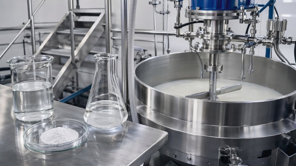
The target is monolayer coverage. For precipitated silica and fumed silica, that translates to approximately 3.5–4.5 µmol/m² of silane — a figure that depends on the specific surface area measured by BET and on the molecular footprint of the silane you are using.
Calculating Your Theoretical Monolayer Dose
The calculation is straightforward and should be done before any trial run. Take the BET surface area of your filler (m²/g), multiply by the molecular footprint of your silane (typically 0.40–0.60 nm² per molecule for common bifunctional silanes), multiply by Avogadro’s number, and you have molecules per gram of filler. Convert to mass using the silane’s molecular weight. For a silica with a BET of 175 m²/g treated with TESPT (molecular weight 538 g/mol, footprint ~0.50 nm²), the theoretical monolayer works out to roughly 0.9–1.1 parts silane per 100 parts filler. If your current formulation calls for 1.5 phr, you are already in the physisorbed zone.
Monolayer silane coverage for precipitated silica is typically achieved at 3.5–4.5 µmol/m², and loading above this threshold adds physisorbed multilayers that do not contribute to interfacial bonding.True
This range is consistent with published surface chemistry literature on silane grafting density on silica and is reproducible through thermogravimetric and elemental analysis methods.
Design of Experiments to Find Your True Optimum
Rather than running one-factor-at-a-time trials — which is still common practice on compounding floors — a 2³ full factorial covering silane loading (0.5, 1.0, 1.5 wt% on filler), treatment temperature (100, 130, 150 °C), and mixing time (2, 4, 6 minutes) will map interaction effects that single-variable trials miss. Response variables should include bound rubber content, tensile strength, and elongation at break. Temperature and time interact strongly: a short mix at 150 °C can match a long mix at 100 °C on bound rubber but produce different silanol conversion profiles that only show up in aging data.
A typical DOE outcome: loading above 1.0 wt% shows diminishing returns on Payne effect reduction at 130 °C and 4 minutes, while the temperature–time interaction dominates below 0.9 wt%. That kind of result is invisible without a factorial structure.
Inline and At-Line Measurement for Production Control
Three measurement tools belong in any serious silane treatment operation. An NIR probe mounted at the mixer headspace tracks ethanol evolution in real time — ethanol release rate is a direct proxy for hydrolysis and condensation progress, and a plateau in the signal tells you the reaction has stalled or completed. An LOI oven provides at-line quality control on treated filler; the loss on ignition difference between untreated and treated filler correlates directly to grafted silane content. A water contact angle goniometer takes under five minutes per sample and confirms surface energy shift — untreated silica typically sits below 30°, properly treated silica should read 65–85° depending on the silane functional group.
SPC Control Chart Setup and Capability Targets
Once your process is defined, run X-bar and R charts on LOI with control limits set at ±3σ from your established mean. A Cpk of 1.33 or higher is the minimum acceptable capability for treated filler LOI — below that, you are shipping product with unpredictable interface quality. Establish baseline capability at line startup. Re-run a full capability study after any raw material source change, including silane supplier, silica grade, or even silica production batch if BET variance exceeds 10 m²/g lot-to-lot.
What This Looks Like as a Cost Reduction
Start from a baseline of 1.5 wt% silane on silica. A structured DOE identifies 0.9 wt% as the point achieving equivalent Payne effect reduction and tensile performance. For a plant processing 800 tonnes of silica annually, that 0.6 percentage point reduction — multiplied by silane cost per kilogram and filler throughput — produces annual material savings in a range that justifies the DOE investment many times over. The exact figure depends on silane grade, current contract pricing, and whether you are buying treated filler externally or treating in-house, but the direction is consistent across every plant scenario where the baseline was set by formulator habit rather than surface chemistry calculation.
Frequently Asked Questions About Silane Coupling Agent Application
These are the questions that come up repeatedly on production floors, in procurement reviews, and during quality audits. Short answers are given first, followed by the operational detail you actually need.
Can I use the same silane for both glass fiber and mineral filler treatment?
Functionally yes, provided the organofunctional group matches your resin system. The chemistry does not change between substrates. What changes significantly is concentration and method. Glass fiber sizing runs at 0.5–1.0 wt% aqueous solution, where LOI (loss on ignition) control is tight — typically targeting 0.1–0.5 wt% add-on depending on the fiber application — because over-treatment on fiber degrades bundle integrity and sizing compatibility. Mineral filler treatment, by contrast, typically calls for 1.0–2.0 wt% solution and requires higher-energy mixing to achieve uniform surface coverage across a high-surface-area powder. Running both substrates at the same concentration and expecting equivalent results is a common upstream mistake that shows up downstream as inconsistent mechanical properties.
How do I know if my silane treatment is actually working before I run a full compound batch?
Three fast diagnostic checks before you commit a full batch:
- Water contact angle: A well-treated hydrophilic filler such as calcium carbonate or silica should shift from a contact angle below 10° (essentially zero, water spreads instantly) to 60–90° after proper silane treatment. Anything below 40° suggests incomplete coverage or inadequate drying.
- Dispersibility in low-polarity solvent: Drop a small quantity of treated filler into a non-polar solvent like xylene or mineral spirits and observe whether it disperses or clumps and sinks. Untreated or under-treated mineral filler sinks rapidly; well-treated filler disperses or floats.
- LOI spot check: A simple muffle furnace LOI against your target add-on takes under an hour and catches gross under- or over-treatment before you waste a mixer charge.
What is the shelf life of a pre-hydrolyzed silane solution?
Use hydrolyzed aminosilane and epoxysilane solutions within 4–8 hours of preparation. Both chemistries oligomerize quickly once hydrolysis begins, and solution past this window forms gels that deposit unevenly and reduce bonding efficiency. Vinylsilane and methacrylsilane solutions buffered to pH 4–5 and stored at 5–20 °C can remain usable for up to 24 hours, but even these should be prepared fresh for critical applications. Never seal a hydrolyzed solution container without venting — CO₂ and alcohol vapor pressure build, and sealed containers have failed unexpectedly during storage.
Is it possible to over-treat a filler with silane?
Yes, and it is more common than most compounders expect. Excess silane forms physisorbed multilayers on top of the chemically bonded monolayer. These multilayers act as an internal plasticizer at the interface rather than a coupling agent. Practical signs: abnormally low compound viscosity at high filler loading, reduced tensile modulus or hardness compared to a reference batch, and a greasy or clumped appearance in the treated filler before compounding. If you see these, reduce silane loading in 10–15% increments and recheck mechanical properties.
Physisorbed silane multilayers reduce reinforcement efficiency and can lower composite modulus even while increasing silane cost.True
Chemically bonded silane monolayers create the coupling bridge between inorganic filler and organic matrix. Additional physisorbed layers are not covalently anchored and behave as a low-molecular-weight plasticizer at the interface, confirmed by multiple composite mechanics studies and consistent with production observations of modulus drop at excessive silane loadings.
What is the difference between KH-550, KH-560, and KH-570?
These three grades cover the majority of thermoset and UV-cure applications but are not interchangeable.
| Grade | Chemical name | Primary reactive matrix | Typical use case |
|---|---|---|---|
| KH-550 | 3-Aminopropyltriethoxysilane | Epoxy, phenolic, polyamide | Epoxy composites, GFR plastics, mineral-filled nylon |
| KH-560 | 3-Glycidoxypropyltrimethoxysilane | Epoxy, polyurethane, acrylate | Adhesives, sealants, moisture-resistant laminates |
| KH-570 | 3-Methacryloxypropyltrimethoxysilane | UV-cure, peroxide-cure acrylic, polyester | Dental composites, UV-coatings, SMC/BMC compounds |
Using KH-550 in a peroxide-cure polyester system, for example, leaves the amino group unreacted with the matrix and provides little more than filler wetting — mechanical improvement will be marginal and you will not understand why until you audit the chemistry selection.
Can silane coupling agents be used on carbon black or carbon fiber?
Standard hydrolytic silane chemistry depends on surface hydroxyl groups for bonding. Carbon black in its untreated state carries insufficient surface hydroxyl density to support meaningful silane grafting, so direct application adds cost without measurable adhesion improvement. Plasma treatment or controlled oxidative acid treatment of carbon surfaces introduces hydroxyl and carboxyl functionality that makes silane bonding viable — but the effectiveness varies with carbon black grade, surface area, and treatment intensity, so validate with contact angle and compound mechanical data rather than assuming it will work. For carbon fiber, commercial sizing formulations typically combine silane with a compatible film-former resin. The silane handles inorganic surface bonding; the film-former handles fiber bundle integrity and compatibility with the matrix resin.
How does production environment humidity affect silane application?
High ambient relative humidity — above 70% RH — accelerates hydrolysis of neat or dilute silane before it contacts and orients on the substrate surface. The result is premature oligomerization in the air film or in the applicator, depositing irregular silane clusters rather than a uniform monolayer. For metal pretreatment, the practical rule is to apply silane when ambient RH is below 60% and to move substrates into the dryer or oven immediately after application. In high-humidity climates or during summer production shifts, scheduling silane application to early morning hours when temperature and humidity are lower is a simple operational adjustment that pays off in coating adhesion consistency.
Partnering With SiliconChemicals for Consistent Silane Supply and Application Support
Getting the chemistry right on the production floor is only half the equation. The other half is knowing that the silane arriving at your dock next month is identical — functionally and analytically — to the batch you qualified last quarter. Process drift caused by supplier variability is one of the quieter sources of scrap and rework in silane-dependent operations, and it rarely shows up on the incoming inspection report until a compounder or coater is already chasing a failing peel strength or a wet-out problem on glass fiber.
Manufacturing Quality That Shows Up on the Certificate of Analysis
SiliconChemicals operates dedicated silane synthesis and purification lines where GC assay, moisture content, refractive index, and APHA color are measured on every production batch — not sampled periodically, but every batch. The certificate of analysis ships with each order. For key accounts running validated production processes, third-party audit access to batch records is available under a standard confidentiality agreement.
SiliconChemicals tests GC assay, moisture content, refractive index, and APHA color on every production batch, with CoA provided per shipment.True
This reflects the company's stated quality control procedure applied to all silane synthesis batches, consistent with industrial silane supplier practice for specification-critical products.
Tight moisture control matters particularly for chlorosilane-derived and acetoxy-functional grades, where even marginal moisture ingress during storage shifts the hydrolysis equilibrium before the product reaches your mixing equipment. Receiving a silane at 200–400 ppm moisture rather than the specified ≤50 ppm can accelerate pre-condensation in the drum and produce gel particles that clog spray nozzles or create localized over-treatment on filler surfaces.
Product Range Built for Industrial Breadth
The standard KH series covers the workhorse grades — KH-550 (aminopropyltriethoxysilane), KH-560 (glycidoxypropyltrimethoxysilane), KH-570 (methacryloxypropyltrimethoxysilane), KH-792 (diaminofunctional), and KH-845 equivalents — all cross-referenced to internationally recognized A-series designations so procurement teams switching sources don’t need to re-qualify nomenclature.
Beyond the standard monomers, the range includes oligomeric silane formulations for operations where reduced VOC emission during open-surface treatment or spray application is a regulatory or workplace exposure priority. Oligomeric grades also improve handling consistency when operators are applying dilute aqueous solutions in poorly ventilated spaces. Blocked aminosilanes are stocked for high-temperature processing windows — relevant in nylon and engineering thermoplastic compounds where a free primary amine would catalyze premature reaction during compounding. Sulfur-functional silanes equivalent to TESPT and TESPD are available for tire tread and technical rubber applications where silica reinforcement efficiency is tied directly to the polysulfidic bridge chemistry.
Technical Application Support With Real Engineering Depth
Application support is not a sales brochure exercise. SiliconChemicals’ application engineers review compound formulations, identify silane loading and addition sequence issues, and where a customer is introducing silane treatment for the first time, can conduct on-site process audits. The laboratory screening service — covering loss on ignition for treated fillers, contact angle measurement, and mechanical performance in standard rubber or composite test compounds — gives development engineers comparative data before committing to a full production trial.
Supply Chain Reliability Across More Than 30 Markets
Strategic inventory is maintained at China warehouse locations with export documentation prepared for more than 30 destination countries. Standard lead time for stocked grades runs 7–15 days from order confirmation; custom formulations or large-volume contract orders typically require 25–35 days depending on synthesis scheduling. Full REACH, RoHS, and SDS documentation packages are provided as standard — not on request.
Starting a Technical Dialogue
To get an application recommendation, the engineering team needs to know your substrate type and surface chemistry, your polymer or resin matrix, the processing temperatures and shear conditions involved, and any existing performance or regulatory constraints. Bring those inputs to the first conversation and the screening can move quickly. Sample requests, formulation consultations, and process audit inquiries go through SiliconChemicals’ application engineering team — no commitment required to start the technical discussion.