Nanoscale fillers — silica, carbon nanotubes, nanoclay, aluminum oxide — promise extraordinary mechanical and barrier properties on paper. In practice, unmodified nanoparticles aggregate aggressively, and their hydroxyl-saturated surfaces bond poorly to organic polymer matrices. The result is stress concentration at every particle boundary: fatigue cracks initiate early, impact resistance drops, and compounders watch expensive high-surface-area materials deliver maybe 20–30% of their theoretical reinforcement. At commercial scale, that gap between lab data and production reality translates directly into reformulation cycles, scrap rate, and lost contracts.
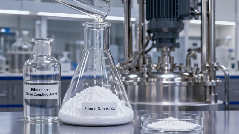
Silane coupling agents act as molecular bridges at the inorganic-organic interface in nanocomposites. A bifunctional silane hydrolyzes and condenses onto filler hydroxyl groups through its alkoxysilane head, while its organofunctional tail co-reacts or physically entangles with the polymer matrix. This dual bonding mechanism reduces interfacial voids, suppresses filler agglomeration, and can raise interfacial adhesion strength by 40–80% versus untreated fillers — the exact improvement depending on surface chemistry, matrix polarity, and silane loading density.
What makes this chemistry genuinely interesting at the nanoscale is the geometry problem it solves. A nanosilica particle with 200 m²/g BET surface area presents an almost incomprehensible density of reactive sites — and getting the right silane, at the right surface coverage, through the right treatment process, is the difference between a product that performs and one that looks good only in a data sheet. The sections that follow work through how that is actually done.
 molecular bridging between nanosilica particles and polymer matrix in an industrial compounding environment](https://siliconchemicals.com/wp-content/uploads/2026/06/silane-coupling-agent-nanotechnology-advanced-materials-01-hero.jpg)
Molecular Mechanisms: How Silane Coupling Agents Bond at the Nano-Interface
The chemistry sounds straightforward on paper: a bifunctional molecule bridges an inorganic surface and an organic matrix. In practice, getting that bridge to form correctly — consistently, at scale, on surfaces with 200 m²/g of reactive area — requires understanding every step of the reaction sequence and where each one can go wrong.
The Four-Step Reaction Sequence
The grafting process follows a well-established hydrolysis-condensation pathway, but each step carries its own process sensitivity.
Step 1 — Hydrolysis. In the presence of moisture, the alkoxy groups (–OCH₃ or –OC₂H₅) cleave to generate reactive silanol groups (Si–OH) and release methanol or ethanol. Reaction rate here depends heavily on pH: the window of pH 4–5, typically achieved with dilute acetic acid, gives controlled, partial hydrolysis. Go too alkaline and you accelerate condensation in solution before the silane ever contacts the surface — you end up treating the mixing vessel, not the filler.
Step 2 — Hydrogen bonding. The freshly formed silanols approach surface hydroxyl groups (silanol groups on nanosilica, hydroxyl-decorated edges on graphene oxide, Ti–OH on nano-TiO₂) and form hydrogen bonds. This is a reversible physisorption stage. Temperature matters here: too high and desorption competes with the next step; too low and diffusion through the adsorbed water layer limits contact.
Step 3 — Condensation and covalent bond formation. Water loss drives the formation of covalent Si–O–M bonds (M = Si, Ti, Al depending on filler type). This is the step that locks the silane to the surface permanently. Incomplete condensation — often caused by insufficient cure temperature or residual solvent blocking surface sites — leaves the coupling agent physisorbed rather than chemisorbed. The result looks correct in solution but fails under mechanical or thermal stress in the final composite.
Step 4 — Lateral crosslinking. Adjacent silanol groups on neighboring grafted molecules condense with each other, forming a siloxane network (Si–O–Si) across the surface. A properly formed monolayer shows lateral crosslinking that reinforces the interface without burying the organofunctional group that needs to remain accessible to the polymer matrix.
Why Nanoscale Surfaces Change the Equation
Fumed silica used in nanocomposite work typically carries a specific surface area of 50–400 m²/g, depending on grade and production method. That extreme surface-area-to-volume ratio means silane consumption scales sharply — and so does the risk of multilayer formation. At loadings above roughly 4–5 wt% relative to filler (or beyond approximately 4 μmol/m² surface coverage), excess silane molecules condense on top of the first grafted layer rather than on the surface itself. That outer layer bonds poorly to anything, acts as a weak boundary layer, and can actually reduce interfacial strength below that of untreated filler. Optimal monolayer coverage for most nanosilica grades falls in the 2–4 μmol/m² range, which translates to 1–5 wt% silane loading depending on surface area and molecular weight of the specific silane chosen.
Carbon nanotubes and graphene oxide introduce additional complexity. Their surface chemistry is less uniform — CNT sidewalls are relatively inert, while carboxylic acid and epoxide groups cluster at defect sites and edges on graphene oxide. Silane grafting on these substrates often requires oxidative pre-treatment to generate enough reactive sites, and competitive adsorption between silane molecules and residual processing surfactants can suppress coverage in ways that simple titration won’t detect.
Multilayer silane formation on nanoparticle surfaces reduces composite interfacial strength rather than improving it.True
Excess silane beyond monolayer coverage creates a poorly crosslinked boundary layer with low cohesive strength. This layer fails preferentially under load, making treated filler perform worse than untreated filler in mechanical testing — a failure mode well-documented in filled elastomer and epoxy composite literature.
Matching Organofunctional Groups to Matrix Chemistry
The inorganic end of the silane handles surface attachment. The organofunctional end must be chemically compatible — ideally co-reactive — with the polymer matrix. Getting this wrong doesn’t always produce obvious mixing problems; sometimes it simply limits adhesion improvement to 15–20% when the chemistry, done correctly, could deliver 40–80%.
| Functional Group | Common Silane | Target Polymer Systems | Representative Applications |
|---|---|---|---|
| Amino (–NH₂) | APTES (3-aminopropyltriethoxysilane) | Epoxy, polyamide, polyurethane | Nanosilica-reinforced epoxy coatings, fiber sizings |
| Epoxy (glycidoxy) | GPTMS | Epoxy, polyesters, acrylics | Nano-TiO₂ in UV-curable coatings, adhesives |
| Methacryloxy | MAPTMS | Unsaturated polyester, acrylics, PMMA | Glass/nano-SiO₂ in dental composites, FRP |
| Mercapto (–SH) | MPTMS | Sulfur-cured rubbers, polysulfide sealants | Carbon black and nanosilica in tire compounds |
| Vinyl | Vinyltrimethoxysilane | Polyolefins, silicone rubber, crosslinked PE | Cable insulation, silicone-nanoparticle hybrids |
Amino silanes are often the default choice in lab settings because they are water-soluble and easy to handle. That convenience has a cost: amino groups are susceptible to carbonation in storage and can form hydrogen-bonded multilayers on silica more readily than most other functional groups, making process control especially important when scaling from bench to production quantities.
Functionalizing Nanoparticles: Surface Treatment Protocols for Silica, Titania, and Carbon Nanomaterials
Getting the surface chemistry right before nanoparticles ever touch your matrix is the difference between a composite that performs and one that fails at the interface — usually under the worst possible service conditions. Each nanoparticle family has its own surface chemistry, its own failure modes during treatment, and its own tolerance for process variation.
Nanosilica: Dry vs. Wet Treatment and What Each Buys You
Precipitated and fumed nanosilica carry dense silanol populations (typically 4–8 OH groups/nm²), which makes them genuinely receptive to silane chemistry — but that same hydrophilicity drives irreversible hydrogen-bonded agglomeration if you don’t treat early in the process chain.
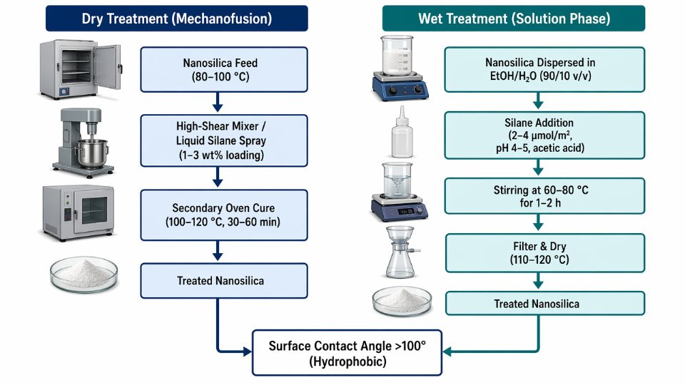
Dry (mechanofusion) treatment suits continuous compounding lines. Silane loading runs 1–3 wt% relative to filler, metered as a liquid spray into a high-shear mixer while the silica is at 80–100°C. The heat drives hydrolysis and condensation without free water accumulation. Cure is completed in a secondary oven stage at 100–120°C for 30–60 minutes depending on silane type and bed depth. Throughput is good; coating uniformity depends heavily on mixer tip speed and spray droplet size — uneven distribution shows up immediately as streaks of untreated aggregate in the final compound.
Wet treatment gives better coverage control and suits laboratory-to-pilot scale well. Silica dispersed in ethanol/water (typically 90/10 to 95/5 v/v) at 1–5 wt% solids, silane added at 2–4 μmol/m² relative to measured BET surface area, pH adjusted to 4–5 with acetic acid to catalyze hydrolysis, then stirred at 60–80°C for 1–2 hours before filtering and drying at 110–120°C. The contact angle shift is measurable and dramatic — untreated fumed silica sits at 100° with a propyltrimethoxysilane, confirming true hydrophobic conversion. That shift directly translates to better dispersion torque profiles in rubber compounding and lower moisture uptake in filled epoxy systems.
Nano-TiO₂: Navigating Lewis Acid Surface Sites
Titania surfaces are more chemically hostile to silane chemistry than silica. The Lewis acid Ti⁴⁺ sites compete with silane hydrolysis intermediates and can catalyze premature condensation in solution, producing oligomeric silane deposits rather than a grafted monolayer. This is the single most common reason silane treatment of TiO₂ delivers inconsistent results at scale.
Aminosilanes (e.g., APTES, APTMS) perform well because the amine group coordinates to Ti⁴⁺, anchoring the silane prior to condensation and improving monolayer regularity. For UV-reflective and photocatalytic coating applications, fluoroalkylsilanes offer the added benefit of reducing surface energy substantially while partially suppressing photocatalytic activity — a deliberate trade-off worth understanding. Photocatalytic activity reduction of 30–60% has been reported after dense fluoroalkylsilane treatment, which matters for outdoor polymer composites where TiO₂-catalyzed matrix degradation is a real service-life threat.
Silane surface treatment of nano-TiO₂ can partially suppress photocatalytic activityTrue
Dense silane monolayers physically block reactive surface sites and reduce UV-excited hole-electron pair accessibility, lowering photocatalytic degradation rates — documented in peer-reviewed coatings research and consistent with surface area blocking models
Keep reaction temperatures for TiO₂ treatment below 90°C in aqueous systems; above that, anatase-to-rutile phase transitions can begin at the nanoscale, altering both optical and mechanical behavior.
CNTs and Graphene Oxide: Oxidation First, Then Grafting
Pristine CNTs and as-synthesized graphene are chemically inert. Silane chemistry has nothing to grab. The mandatory first step is oxidative functionalization — typically reflux in concentrated H₂SO₄/HNO₃ (3:1 v/v) for 2–4 hours, or milder persulfate oxidation for graphene oxide synthesis — generating surface hydroxyl, carboxyl, and epoxide groups that can participate in subsequent silane condensation.
After oxidation, two grafting routes exist. Covalent silane grafting reacts silanol groups from hydrolyzed silane directly with surface –OH groups at 60–80°C in ethanol/water; this achieves permanent bonding but can damage CNT electronic properties if oxidation was aggressive. Non-covalent wrapping using silane-functionalized polymers or bifunctional silanes preserves CNT conductivity but gives lower interfacial shear strength. For structural epoxy composites where tensile modulus is the design metric, covalent grafting wins. Silane-treated CNT/epoxy systems show tensile modulus increases of 20–60% over untreated CNT composites at equivalent filler loadings — the range depends primarily on CNT aspect ratio, dispersion quality, and whether agglomerates survive into the final laminate.
Process Variables That Make or Break Surface Treatment
Water content during silane hydrolysis must stay within a narrow window. Too little and hydrolysis is incomplete; too much and silane self-condenses into useless oligomers before it reaches the particle surface. For most alkoxysilanes in ethanol-based systems, 5–15 vol% water is the practical range.
Shear rate during mixing controls whether treated particles re-agglomerate. High-shear dispersers (tip speeds >10 m/s) are needed for fumed nanosilica; excessive shear on CNTs damages tube walls and reduces aspect ratio.
Solvent selection affects both silane hydrolysis rate and nanoparticle wettability. Alcohols are standard; ketones should be avoided with aminosilanes due to Schiff base side reactions that consume the functional group before it reaches the matrix.
Selecting Your Treatment Route
| Production Scale | Nanoparticle Type | Recommended Route |
|---|---|---|
| Lab / pilot (<10 kg batch) | Silica, TiO₂, GO | Wet chemical (solution phase) |
| Continuous compounding line | Fumed silica, precipitated silica | In-situ / dry spray treatment |
| Any scale, heat-sensitive substrates | CNTs, functionalized graphene | Wet chemical, controlled temperature |
| Bulk powder, high throughput | Silica (non-porous) | Vapor-phase silanization |
Vapor-phase silanization — passing silane vapor over a fluidized nanoparticle bed at 120–150°C — eliminates solvent handling entirely and gives excellent coating uniformity for spherical low-porosity particles. It is poorly suited to high-aspect-ratio materials like CNTs, where vapor penetration into bundles is uneven. Match the process to the particle geometry, not to what equipment is already on site.
Performance Impact in Polymer Nanocomposites: Mechanical, Thermal, and Barrier Property Gains
The difference between a silane-treated nanocomposite and an untreated one is not subtle. It shows up in tensile test data, in heat deflection failures during accelerated aging, and — most painfully — in returned packaging film that let oxygen through at twice the specified rate. Understanding exactly where those gains come from, and what governs their magnitude, is what separates a credible material specification from a guess.
Mechanical Property Improvements in Epoxy/Nanosilica Systems
At 5–10 wt% nanosilica loading in epoxy matrices, silane-treated fillers typically deliver tensile strength gains of 30–60% and Young’s modulus increases of 20–50% relative to the neat resin. The spread matters: the lower end reflects systems where silane selection was adequate but not optimized — say, a generic aminosilane on a high-surface-area silica in a bisphenol-A epoxy. The upper end is achieved when the silane functional group is matched precisely to the crosslink chemistry, surface coverage sits in the 2–4 μmol/m² monolayer range, and dispersion protocol eliminates agglomeration before cure.
Untreated nanosilica at the same loading often does the opposite. Poor wetting creates interfacial voids that act as stress concentrators, and tensile strength can actually drop 10–20% below the neat matrix value. That is a failure mode that shows up in quality audits and is frequently misattributed to resin batch variation rather than filler surface chemistry.
Thermal Stability: Tg Shifts and Decomposition Onset
Silane-mediated covalent bonding at the particle surface restricts polymer chain mobility in the interphase region. That constraint raises the glass transition temperature by 10–30°C in well-formulated epoxy and polyimide nanocomposites — a range that depends on filler surface area, silane grafting density, and how completely the interphase participates in the crosslinked network. In polyamide-6 systems reinforced with surface-treated nanosilica, thermal decomposition onset temperatures (measured by TGA at 5% mass loss) shift upward by 15–25°C. For electronic encapsulants or under-hood automotive components, that is not a marginal gain; it can determine whether a part passes IPC or automotive thermal cycling qualification.
Silane surface treatment on nanosilica raises glass transition temperature in epoxy nanocomposites by 10–30°C compared to untreated filler at equivalent loading.True
This range is consistent with published DSC data across epoxy/nanosilica systems; the magnitude depends on silane type, grafting density, and filler volume fraction. Covalent interphase bonding restricts segmental mobility, which DSC detects as a measurable Tg shift.
Barrier Properties in Film Applications
Silane-treated montmorillonite nanoclays and functionalized graphene platelets in polymer films achieve oxygen transmission rate (OTR) reductions of 50–80% compared to neat film, and 30–50% better than films loaded with untreated platelet fillers at the same weight fraction. The mechanism is tortuous path extension: silane treatment improves platelet exfoliation and orientation, lengthening the effective diffusion path for gas molecules. In flexible electronics encapsulation, where OTR targets can be below 0.1 cc/m²/day, the difference between treated and untreated filler can decide whether a product is manufacturable at all.
Impact Toughness: The Stiffness–Toughness Trade-Off
Stiffness gains from silane-treated nanoparticles come with a well-documented cost. As modulus climbs, notched impact strength often falls 15–35% in rigid epoxy systems. Bifunctional silanes that incorporate a flexible spacer group — or hybrid formulations that add a small fraction of rubber-phase compatibilizer alongside the silane-treated filler — can recover 60–80% of that impact loss while retaining most of the modulus gain. This is a genuine engineering balance, not a formulation deficiency, and it needs to be specified explicitly in design briefs rather than discovered during prototype testing.
Comparative Performance Table: Untreated vs. Silane-Treated Filler in Epoxy Nanocomposite
| Performance Metric | Untreated Nanosilica (5–10 wt%) | Silane-Treated Nanosilica (5–10 wt%) | Key Dependency |
|---|---|---|---|
| Tensile strength vs. neat resin | −10% to +15% | +30% to +60% | Silane–matrix chemistry match |
| Young’s modulus vs. neat resin | +5% to +15% | +20% to +50% | Filler dispersion quality |
| Glass transition temperature (Tg) shift | +2°C to +8°C | +10°C to +30°C | Grafting density, surface area |
| OTR reduction (platelet geometry) | 20–35% | 50–80% | Exfoliation degree, aspect ratio |
| Notched impact strength vs. neat resin | −5% to −15% | −15% to −35% (mitigated by bifunctional silanes) | Silane spacer chain length |
The table above reflects representative epoxy nanocomposite data; polyamide or polyimide matrices will shift absolute values but preserve the relative ranking. The performance delta between treated and untreated filler is consistent enough across systems that specifying untreated nanoparticles to save formulation cost is rarely defensible once downstream scrap and rework are factored in.
Silane Coupling Agents in Semiconductor Fabrication and Electronic Materials
Semiconductor fabrication operates at tolerances where a single monolayer of contamination or poor adhesion at a dielectric interface can write off an entire wafer lot. Silane coupling agents have quietly become load-bearing components in this economy — not as bulk additives but as precisely controlled surface chemistries measured in molecules per square nanometer.
Self-Assembled Monolayers and Photolithography Adhesion Promotion
Hexamethyldisilazane (HMDS) has been the photoresist adhesion promoter of choice in semiconductor fabs for decades. Applied by vapor-phase priming at 90–150°C, HMDS converts hydrophilic silanol groups on the SiO₂ wafer surface to trimethylsilyl-terminated, hydrophobic sites. The result is a contact angle shift from roughly 5–20° (bare oxide) to 60–80°, which prevents photoresist delamination during aqueous developer exposure. Without this step, undercutting and pattern collapse rates on sub-100 nm features rise sharply, directly affecting critical dimension uniformity and yield.
HMDS does have limits. At 7 nm nodes and below, resist chemistry has shifted toward chemically amplified resists and EUV-compatible platforms that respond poorly to the relatively non-functional trimethylsilyl surface. Next-generation adhesion promoters — longer-chain alkoxysilanes carrying reactive epoxy or methacrylate groups — provide covalent anchoring to the resist polymer rather than passive hydrophobicity. The tradeoff is tighter process control: alkoxysilane SAM quality depends heavily on surface moisture level, priming temperature (typically 100–180°C), and vapor concentration. A 10–15% deviation in any of these parameters produces incomplete or multilayer deposition, both of which degrade pattern fidelity.
Low-k Dielectric Films and CMP Delamination Prevention
As back-end-of-line (BEOL) interconnect stacks have moved to low-k and ultra-low-k porous dielectric materials, adhesion at the SiO₂/polymer interface has become a yield-limiting variable. These porous films are mechanically fragile — Young’s moduli in the 2–10 GPa range versus 70 GPa for thermal oxide — and the shear stresses imposed during chemical mechanical planarization can initiate delamination if the interface is not chemically reinforced.
Aminosilane primers (3-aminopropyltriethoxysilane, APTES, being the most common) and epoxysilane primers (glycidoxypropyltrimethoxysilane, GPTMS) applied at the SiO₂/polymer dielectric boundary increase peel strength by 40–80%, depending on dielectric porosity and the specific polymer system. The amine group reacts with epoxy-functional dielectric precursors during cure; the alkoxysilane end hydrolyzes and condenses onto the oxide surface. This bifunctional bridging survives the thermal cycling seen in packaging — typically 20–30 cycles from −55°C to 150°C — where an untreated interface would accumulate fatigue damage at each cycle.
Aminosilane primers at low-k dielectric interfaces reduce CMP-induced delamination events compared to untreated interfaces.True
The condensation bond formed between hydrolyzed alkoxysilane groups and SiO₂ surface silanols, combined with covalent reaction at the polymer side, mechanically reinforces an interface that is otherwise held only by van der Waals forces — well-documented in semiconductor process literature and confirmed by peel-strength testing at multiple nodes.
PCB Laminates, Encapsulants, and Moisture Reliability
Epoxy molding compounds (EMCs) used for IC encapsulation rely on silane-treated crystalline silica fillers to achieve the moisture resistance targets set by JEDEC HAST testing (typically 130°C, 85% RH, 96–264 hours depending on component class). Untreated silica creates hydrophilic filler-matrix interfaces that act as moisture ingress pathways. Silane surface treatment — typically an epoxysilane or phenylaminosilane applied at 0.5–2 wt% relative to filler — reduces interfacial moisture uptake and cuts delamination failure rates in HAST by 40–70%, with the actual improvement depending on filler particle size distribution, silane coverage uniformity, and cure profile.
Underfill Materials for Flip-Chip Packaging
Flip-chip underfill must simultaneously manage coefficient of thermal expansion (CTE) mismatch between the die and substrate, maintain low viscosity for capillary flow into fine-pitch bump arrays (pitch now commonly 100–130 μm, trending below 80 μm), and carry high silica filler loading to reduce the CTE of the cured material. These requirements conflict. At 70–80 wt% silica loading — the range needed for meaningful CTE reduction — untreated filler produces viscosities that prevent complete underfill flow before gelation.
Silane-treated silica, with monolayer epoxysilane coverage at 2–4 μmol/m², reduces filler-filler agglomeration and lowers the viscosity of loaded formulations by 30–60% relative to untreated equivalents at the same loading. This is not a marginal improvement. It is often the difference between a formulation that passes and one that fails capillary flow qualification entirely.
2.5D/3D IC Packaging and Heterogeneous Integration
In 2.5D interposer-based packages and 3D stacked dies, the interfacial stack complexity multiplies. A silicon interposer may carry SiO₂ insulation layers, polymer redistribution layer dielectrics, and organic substrate bonding adhesives within a vertical distance of a few micrometers. Each interface is a potential delamination site under the thermal and hygroscopic stresses of assembly and field operation. Fan-out wafer-level packaging (FOWLP) introduces molded compound-to-RDL polymer interfaces that are exposed to sawing stress, reflow excursions, and moisture absorption cycles.
Silane coupling agent selection at each of these interfaces is now a designed-in yield factor, not an afterthought. Formulators working on advanced packaging are specifying silane type, application method, and coverage density as controlled process parameters — the same way they specify lithography chemistry. Getting this wrong at volume production is not a material science discussion; it is a cost-per-good-die problem.
Biomedical Nanotechnology: Silane Functionalization for Drug Delivery, Biosensors, and Implant Coatings
Biomedical applications impose a set of constraints that structural composites never face: the material must perform at physiological pH and temperature, resist enzymatic degradation, avoid triggering immune responses, and in many cases carry a biological payload without denaturing it. Silane coupling agents have carved out a substantial and growing role here — not because they are biologically inert by default, but because their surface chemistry can be precisely tailored to meet each of these demands when the functionalization protocol is executed correctly.
Mesoporous Silica Nanoparticles as Controlled-Release Drug Carriers
MSNs have surface areas in the range of 600–1,000 m² per gram and pore diameters typically between 2 and 10 nm, which makes them attractive scaffolds for drug encapsulation. Raw MSN surfaces carry silanol groups that hydrolyze rapidly and allow uncontrolled drug leakage. Aminosilanes — APTES being the workhorse — graft primary amine groups onto both the outer particle surface and the internal pore walls, providing anchor points for targeting ligands such as folate, transferrin peptides, or antibody fragments. GPTMS (3-glycidoxypropyltrimethoxysilane) offers an epoxide handle instead, useful when the attached ligand contains thiol or amine nucleophiles and the researcher needs a more stable covalent linkage than a simple electrostatic attachment provides.
The silane loading matters enormously here. At low APTES concentrations — below roughly 0.5 mmol per gram of MSN — surface coverage is sparse and drug retention is poor. Overloading above approximately 2 mmol per gram risks pore blockage, dropping drug-loading capacity by 30–60% depending on pore geometry. Optimal functionalization for pH-responsive release typically targets a surface density that leaves the pore aperture partially gated, so that the amine protonation state at endosomal pH (around 5.0–5.5) versus physiological pH (7.4) creates a detectable release differential. Redox-responsive variants use disulfide-bridged silanes that cleave selectively in the elevated glutathione environment inside tumor cells — a chemistry that requires rigorously anhydrous reaction conditions to prevent premature hydrolysis during synthesis.

Biosensor Electrode Surfaces: Density and Orientation Control
For diagnostic biosensors — lateral flow immunoassays, electrochemical glucose sensors, surface plasmon resonance platforms — the silane monolayer is the platform, not the final functional layer. APTES or GOPTS (glycidoxypropyl-terminated silane) deposited on glass, quartz, or indium tin oxide substrates creates the reactive surface onto which antibodies or aptamers are subsequently conjugated.
The critical process variable is surface density. Pack antibody molecules too tightly and steric hindrance blocks the antigen-binding site; too sparsely and sensitivity collapses. Published research consistently shows that antibody surface densities between roughly 1 and 3 ng per mm² yield the best signal-to-noise outcomes, though the exact optimum shifts with molecular weight and orientation. Orientation preservation — anchoring antibodies through the Fc region rather than randomly through any available amine — requires either protein A/G bridging layers or controlled thiol chemistry, which itself depends on the quality and uniformity of the underlying silane monolayer.
Deposition conditions for biosensor applications are tighter than for industrial composite work: solvent composition (anhydrous toluene versus aqueous ethanol versus vapor-phase deposition), humidity during cure, and substrate pre-cleaning protocol all shift contact angle by ±10–15° and XPS nitrogen peak intensity by measurable amounts. A silane film that passes visual inspection can still produce irreproducible biosensor batches if residual water during deposition promotes multilayer polymerization rather than a true monolayer.
Orthopedic and Dental Implant Coatings
PEEK (polyetheretherketone) has become a serious alternative to titanium alloy in spinal and dental implants because of its radiolucency and elastic modulus closer to cortical bone. Its chemical inertness is also its problem — osteoblast adhesion on untreated PEEK is poor, and clinical reports of late-stage implant micromotion failure correlate with inadequate osseointegration at the bone-implant interface.
Silane coupling agents bridge this gap by bonding hydroxyapatite (HA) nanoparticles — particle sizes typically 20–100 nm — to the PEEK surface. The protocol generally involves plasma or UV-ozone activation of PEEK to introduce surface hydroxyl and carboxyl groups, followed by silane treatment (often APTES or MPTMS) to create an intermediate coupling layer, then HA nanoparticle deposition. Pull-off adhesion strength of HA coatings on silane-treated PEEK runs 40–75% higher than on untreated PEEK, depending on plasma activation dose and silane concentration — numbers that translate directly to reduced micromotion under cyclic loading.
Titanium alloy substrates benefit similarly. The native TiO₂ layer reacts readily with trialkoxysilanes, and phosphonate-functionalized silanes in particular improve HA adhesion while also resisting hydrolytic delamination in simulated body fluid at 37°C — a critical durability test for load-bearing implant applications.
Biocompatibility: What the Cytotoxicity Data Actually Says
APTES-functionalized nanoparticles are inherently cytotoxic and unsuitable for in vivo useFalse
Cytotoxicity from APTES-functionalized particles is primarily caused by residual unreacted silane oligomers and byproduct ethanol/methanol, not by the grafted aminopropyl groups themselves. Multiple peer-reviewed studies show that thoroughly washed APTES-MSNs exhibit cell viability above 80% at concentrations below 100 µg/mL in standard MTT assays. The washing protocol — typically three or more cycles in ethanol and water with centrifugation or dialysis — is the controlling variable, not the silane chemistry itself.
This distinction matters operationally. A functionalization batch that skips adequate washing to save two hours of processing time can fail cytotoxicity screening and force a complete lot rejection. Establishing a validated washing protocol and testing residual silane concentration (by TGA or ninhydrin assay for amines) before advancing to cell testing is standard practice in any serious biomedical development lab.
Regulatory and Surface Characterization Requirements
Medical devices incorporating silane-functionalized surfaces fall under ISO 10993 biocompatibility evaluation. Regulators and notified bodies expect documented surface characterization as part of the technical file. The standard analytical toolkit — XPS to confirm element composition and bonding state, ToF-SIMS to map lateral homogeneity, static water contact angle to verify hydrophilicity or hydrophobicity as designed — provides the evidence that the silane coating is present, uniform, and chemically what the specification says it is. Contact angle measurement alone is insufficient; it confirms surface energy change but cannot distinguish a proper monolayer from an uneven multilayer film that happens to produce a similar average reading.
Getting surface characterization right before submission is far less expensive than a regulatory query demanding supplementary data six months into a review cycle.
Energy Storage and Conversion: Silane Chemistry in Batteries, Supercapacitors, and Photovoltaics
Clean energy hardware fails at interfaces. Whether it is a battery separator rupturing under thermal stress, a silicon anode cracking apart after 150 charge cycles, or a perovskite solar cell degrading within weeks of moisture exposure, the root cause is almost always inadequate interfacial chemistry. Silane coupling agents are now embedded across the entire clean energy materials stack — not as an afterthought, but as a primary design variable.
Battery Separators: Ceramic Coatings That Actually Stay Put
Polyethylene separators coated with Al₂O₃ or SiO₂ nanoparticles are standard in high-energy lithium-ion cells, but the coating adhesion problem is frequently underestimated. Without surface treatment, nanoparticle layers delaminate under the mechanical stress of winding and electrolyte swelling, degrading both the thermal shutdown function and electrolyte wettability over time.
Silane pretreatment of the ceramic particles — typically using aminosilanes or methoxysilanes at 1–3 wt% loading relative to filler — bonds the inorganic coating to the polyolefin substrate through a combination of covalent anchoring and mechanical interlocking at the fiber scale. The practical result: puncture resistance improvements of 30–50% compared to uncoated or untreated separators, with the specific gain depending on nanoparticle size distribution, silane type, and coating thickness. Thermal dimensional stability at 150–180 °C also improves measurably, which matters when a cell approaches thermal runaway.
Silicon Anodes: Buying 300% Volume Swing Without Cracking
Silicon’s theoretical capacity advantage over graphite is well known. Its volumetric expansion during lithiation — roughly 280–310%, depending on particle size and lithiation depth — is equally well known and equally brutal on electrode integrity. Nano-Si particles fracture, expose fresh surfaces, consume electrolyte forming unstable SEI layers, and capacity fades fast. Many cells using untreated nano-Si struggle past 150–200 cycles in half-cell configurations.
Aminosilane and vinylsilane coatings applied to nano-Si particles address two failure modes simultaneously. The silane layer acts as a compliant interface that partially accommodates strain during expansion, and it presents functional groups to the electrolyte that promote a more stable, thinner SEI layer. Published half-cell data from academic and industrial labs consistently shows cycle life extending from the 150–200 cycle range to 500 cycles or beyond when silane functionalization is properly optimized — exact figures depend on particle size (50–200 nm range), silane chemistry, and binder system. Vinylsilanes show particular promise in systems where crosslinking with the binder is intentional.
Silane-functionalized nano-Si anodes can extend half-cell cycle life from around 200 cycles to over 500 cycles compared to untreated particles.True
This range is consistent with peer-reviewed literature on aminosilane and vinylsilane surface treatments of nano-Si, where improved SEI stability and strain accommodation are the primary mechanisms. The exact numbers depend on particle size, silane loading, electrolyte composition, and cycling conditions.
Supercapacitor Electrodes: Adding Pseudocapacitance Without Killing Conductivity
Carbon nanotube and graphene electrodes in supercapacitors store charge primarily through electrostatic double-layer mechanisms. Introducing pseudocapacitive functional groups — carbonyl, amine, or phosphonate groups via silane functionalization — can increase specific capacitance by 20–40%, a meaningful gain when the baseline is already measured in hundreds of F/g. The risk is conductivity loss. Silane chemistry allows targeted, low-density functionalization that avoids the resistive overlayers that oxygen plasma or acid treatment can produce. Silane loading needs to stay below roughly 2–3 wt% relative to carbon to keep sheet resistance penalty acceptable.
Photovoltaics: Thin Interlayers with Outsized Performance Impact
In dye-sensitized solar cells, aminosilane or phosphonosilane monolayers at the TiO₂/dye interface reduce surface trap states, slowing recombination measurably. Perovskite solar cells face a harder problem: moisture ingress at the TiO₂/perovskite and TiO₂/HTL interfaces degrades performance within days under ambient conditions. Hydrophobic silane interlayers — fluoroalkylsilanes or phenyltrimethoxysilane derivatives — applied at those interfaces act simultaneously as a moisture barrier and a recombination suppressor. Reported power conversion efficiency improvements fall in the 0.5–1.5 percentage point range across the published literature, with the upper end achieved when the silane treatment is combined with interface passivation. That range may sound modest, but at commercial scale it translates directly to module revenue per unit area.
Wind Turbine Blades: Fatigue Is the Real Killer
A 70-meter blade sees tens of millions of load cycles over its service life. Glass fiber reinforced epoxy laminates without adequate fiber-matrix adhesion accumulate microcracks progressively, and delamination initiates at stress concentrations long before design life is reached. Silane sizing on glass fiber — applied at the fiber drawing stage, typically epoxysilane or aminosilane at 0.3–1.0 wt% on fiber — improves fiber-matrix shear strength and, critically, fatigue crack propagation resistance. Laminates with properly silane-sized glass fiber routinely demonstrate 30–50% longer fatigue life in cyclic flexure testing compared to poorly sized or re-processed fiber where the sizing has been compromised. In procurement terms, switching to an incompatible or degraded silane sizing to chase a lower fiber price is a decision that shows up in blade warranty claims two to four years later, not on the invoice date.
Selecting the Right Silane Coupling Agent: A Systematic Decision Framework for Engineers
Getting silane selection wrong rarely produces an obvious catastrophe on day one. What it produces is a gradual accumulation of problems — elevated scrap rates, delamination at elevated service temperatures, reduced shelf life in humid storage — that take weeks to trace back to the interface. The five-step framework below is designed to cut that diagnostic loop short.
Step 1 — Identify the Substrate and Its Surface Hydroxyl Density
Start here, not with the polymer. The silane’s alkoxy groups can only graft where surface silanols or equivalent reactive hydroxyls exist. Siliceous substrates (fumed silica, precipitated silica, glass fiber, quartz) carry high hydroxyl densities — typically 4–8 OH/nm² — and respond well to trialkoxysilanes across almost the full functional-group range. Metallic oxides such as alumina, titania, and zinc oxide have lower and more variable hydroxyl densities; they often require pre-treatment with dilute acid or prolonged humidity conditioning to activate the surface before silanization. Calcium carbonate and carbon-based substrates (carbon black, graphene, CNT) are more demanding: carbonates react poorly with standard alkoxysilanes unless carboxy-functional or amine-functional variants are used, while carbon nanomaterials need prior oxidative functionalization to introduce the anchor sites the silane needs. Nail the substrate chemistry first, and half the selection decision is already made.
Step 2 — Match Organofunctional Groups to Matrix Cure Chemistry
The table below captures the core compatibility logic. Mismatches here are a leading cause of adhesion failure in compounding operations.
| Matrix / Cure Chemistry | Preferred Organofunctional Group | Notes |
|---|---|---|
| Epoxy (amine-cured) | Amino (APTES, AMEO) | Reacts directly with epoxide; raises pot-life awareness |
| Epoxy (anhydride-cured) | Epoxy (GPTMS) | Avoids side reactions with anhydride hardener |
| Polyurethane | Amino, isocyanate, ureido | Ureido grades give extended open time |
| Unsaturated polyester / vinyl ester | Methacryloxy (MEMO) | Participates in free-radical cure; timing matters |
| Natural rubber / sulfur-cured elastomer | Mercapto, polysulfidic (TESPT) | Bis-silane grades offer better scorch safety |
| Thermoplastic (PP, PA, TPE) | Vinyl, amino, or reactive grafting grades | Requires melt-reactive coupling or pre-treatment route |
Step 3 — Evaluate Processing Condition Constraints
A silane that works beautifully in a lab solution-blending experiment may be impractical in a twin-screw extruder running at 240 °C. Trimethoxy variants hydrolyze faster than triethoxy grades — useful in waterborne aqueous systems, but a pot-life liability in two-component formulations where working time matters. Melt compounding rules out silanes with low thermal stability thresholds; check TGA onset temperatures against your barrel temperature profile with at least a 20–30 °C safety margin. VOC profile is increasingly a procurement constraint, not just an EHS checkbox — waterborne treatment systems eliminate most of the alcohol byproduct concern but require pH control and adequate drying capacity downstream. Match the silane to the process you actually run, not the idealized lab version.
Step 4 — Run the Minimum Analytical Validation Battery Before Scale-Up
FTIR confirms the silane is on the surface (look for Si–O–Si stretching at 1050–1130 cm⁻¹ and disappearance or shift of surface Si–OH at ~960 cm⁻¹). TGA quantifies grafting density: mass loss between roughly 200–600 °C, after subtracting physisorbed water loss below 150 °C, gives grafted organic loading. Target the 2–4 μmol/m² monolayer window; below it you have insufficient coupling, above it you risk multilayer buildup that reduces crosslink efficiency. Contact angle measurement confirms the surface polarity shift — a treated hydrophilic silica should move from less than 10° to 60–90° water contact angle depending on the functional group. DMA on a compounded sample closes the loop: a well-silanized system shows a measurable increase in storage modulus at the glass transition region and reduced tan δ peak magnitude, both indicators of genuine interfacial stress transfer.

Step 5 — Optimize Cost-Performance Without Sacrificing Interface Quality
Bifunctional silanes carrying two different organofunctional groups deliver versatility but cost 30–80% more per kilogram than standard monosilanes, depending on synthesis complexity and order volume. In many rubber and thermoplastic applications, blending a primary coupling silane with a smaller proportion of a hydrophobic co-silane (vinyl or propyl grades) improves dispersibility without paying the full bifunctional price premium. Solvent-based treatment systems give tighter control over deposition uniformity on low-surface-area fillers but add solvent recovery cost; waterborne systems are cheaper to run at scale once the pH and dilution protocol is locked in. The crossover point typically falls somewhere between 500–2,000 kg/batch scale, depending on your drying and recovery infrastructure.
Blending a primary coupling silane with a hydrophobic co-silane can achieve comparable dispersion and adhesion performance to a single premium bifunctional silane at lower total formulation cost in many elastomer applications.True
This is well-established practice in rubber compounding: bis-silane grades like TESPT are often diluted with inert or hydrophobic silanes to control scorch and cost. The strategy works when matrix reactivity requirements are met by the primary coupling agent alone.
SiliconChemicals’ product range — spanning vinyl, amino, epoxy, mercapto, methacryloxy, fluorosilane, and specialty bifunctional series — means that working through these five steps with their technical team produces a single-source specification rather than a fragmented multi-supplier bill of materials. That consolidation alone reduces incoming QC burden and simplifies regulatory documentation, two factors procurement managers consistently undervalue until the audit comes.
Quality Assurance, Supply Chain Reliability, and Regulatory Compliance for Industrial Buyers
Procurement managers who specify silane coupling agents for nanocomposite or electronics applications quickly discover that grade selection is only half the problem. The other half is ensuring that what arrives on the plant floor matches what the R&D team qualified — batch after batch, month after month. Getting this wrong means inconsistent surface coverage, adhesion failures in the field, or a regulatory non-conformance that halts a product line.
Critical Quality Parameters to Write Into Every Purchase Contract
Four parameters belong in every specification sheet and Certificate of Analysis (CoA) requirement.
Purity by GC should be ≥98% for industrial polymer applications and ≥99% for electronics or biomedical grades. Impurities — typically unreacted chlorosilane residues, disiloxanes, or alcohol carry-overs from the alcoholysis synthesis route — compete for surface hydroxyl sites and reduce effective grafting density. A 1–2% impurity load sounds minor but can reduce monolayer coverage efficiency measurably, particularly on nanosilica with high surface area (150–400 m²/g).
Moisture content by Karl Fischer titration must be specified at <100 ppm for moisture-sensitive grades such as vinyl, epoxy, and methacryloxy silanes. Moisture accelerates pre-hydrolysis in the drum, forming oligomeric siloxanol species that are too large to penetrate tight nanoparticle agglomerates. If you receive material at 300–500 ppm water and proceed without re-testing, expect reduced coupling efficiency and batch-to-batch scatter in mechanical test data.
Hydrolysis rate index (sometimes reported as pH of a 1% aqueous solution or as a kinetic half-life value under standardized conditions) matters most for in-situ surface treatment processes where the silane hydrolyzes directly in an aqueous slurry. Slow-hydrolyzing grades suit dry-blend compounding; fast-hydrolyzing grades suit slurry or solution treatment of nanoparticles. Specify the applicable process and require the supplier to confirm grade suitability with data — not just a product name.
Color by APHA ≤20 is the threshold for electronics-grade and optical-application materials. High color — typically from iron contamination or thermal degradation during distillation — does not always correlate with reduced chemical activity, but it flags process control lapses that may affect other parameters you cannot see.
Batch-to-Batch Consistency and the Production Scale Variable
Chlorosilane alcoholysis is the dominant synthesis route for commercial silane coupling agents. At pilot scale (1–10 tonne batches), temperature control and residence time in the reactor are tighter, producing narrower GC purity distributions. At full commercial scale (50–200 tonne campaigns), heat transfer limitations can widen the impurity profile by 0.3–0.8 percentage points unless the plant has invested in cascade distillation and inline GC monitoring. This is not a theoretical concern — formulators running tight nanocomposite specifications have traced adhesion lot failures directly to commercial-scale production batches from suppliers without adequate process controls.
Mandate in your purchase contract: full GC chromatogram (not summary purity only), Karl Fischer value, APHA color, refractive index, and specific gravity on every CoA. Request a retained sample program for high-volume contracts so disputed lots can be arbitrated against a physical reference.
| Parameter | Standard Industrial Grade | Electronics / Optical Grade | What Varies |
|---|---|---|---|
| GC Purity | ≥98% | ≥99% | Synthesis route, distillation stages |
| Water Content (KF) | <200 ppm | <100 ppm | Drumming atmosphere, seal integrity |
| APHA Color | ≤30 | ≤20 | Raw material iron content, distillation temp |
| Hydrolysis Rate | Supplier-stated | Verified by independent test | pH, solvent system, application process |
Regulatory Compliance Landscape
REACH SVHC screening applies to any silane coupling agent supplied into the EU or used in articles exported there. Most standard aminosilanes (e.g., APTES, AMEO) and vinylsilanes do not appear on the current SVHC candidate list, but mercaptosilanes warrant careful review — 3-mercaptopropyltrimethoxysilane carries consideration flags in several downstream use restriction discussions. Require your supplier to provide an up-to-date REACH compliance declaration and a Safety Data Sheet that reflects the current ECHA candidate list, not a document dated three years ago.
For electronics applications, RoHS 2 (Directive 2011/65/EU as amended) is relevant where the silane is a functional component in a homogeneous material layer in electronic equipment. Confirm absence of restricted substances — particularly cadmium, lead, and hexavalent chromium — which can appear as trace contaminants from catalyst residues in poorly controlled synthesis.
California Proposition 65 requires specific attention for amino and mercapto silanes in products sold or manufactured in California. Some hydrolysis or thermal degradation products of these classes — not necessarily the silane itself — carry Prop 65 listing status.
3-Aminopropyltriethoxysilane (APTES) is not itself listed as a California Proposition 65 chemical, but formulated products containing it may require assessment if they generate listed byproducts during processing.True
Prop 65 listings target specific chemicals; the parent silane may not be listed while thermal or hydrolytic breakdown products in a specific process could fall under listed substances. Always conduct a product-specific legal review.
Supply Chain Positioning and Risk Mitigation
China’s Zhejiang and Jiangsu provinces host the densest concentration of organosilicon raw material producers, chlorosilane intermediates suppliers, and silane coupling agent manufacturers anywhere in the world. SiliconChemicals operates within this cluster, which translates into raw material lead times measured in days rather than weeks, and the ability to maintain strategic buffer inventory for global customers without carrying the cost premium that geographically isolated producers must pass through.
Redundant production lines matter when a single reactor goes down for maintenance or an unplanned shutdown. Buyers running high-volume continuous compounding operations — rubber, coatings, adhesives — cannot absorb a four-week supply gap. Confirm with any supplier whether they operate parallel production trains for your grade and what their demonstrated recovery time has been after a process interruption.
Packaging, Storage, and Shelf-Life Management
Moisture-sensitive silane coupling agents — virtually all alkoxy-functional grades — should arrive in nitrogen-blanketed, sealed drums with moisture-barrier liners. Check the drum seal on receipt; a compromised seal on a 200-liter drum can raise water content from 500 ppm within days in a humid warehouse environment.
Recommended storage: cool, dry conditions below 25°C, away from direct sunlight and ignition sources. Under these conditions, typical shelf life runs 12–24 months depending on functional group sensitivity — vinyl and epoxy silanes are more stable than amino and mercapto grades, which are susceptible to oxidation and self-condensation over time.
For inventory held beyond 18 months, re-test GC purity and Karl Fischer before use. Do not rely on the original CoA for aged stock. A re-test protocol written into your internal material management procedure costs almost nothing and prevents the far larger cost of a nanocomposite production run built on out-of-specification coupling agent.
Frequently Asked Questions About Silane Coupling Agents in Nanotechnology
Are “silane coupling agent” and “surface modifier” interchangeable terms?
They are not, and confusing them leads to failed formulations. A silane coupling agent is specifically bifunctional: one end hydrolyzes and condenses onto an inorganic surface (silica, metal oxide, glass), the other end carries an organofunctional group — amine, epoxy, methacrylate, vinyl — that reacts covalently with the polymer matrix. The molecule physically bridges two incompatible phases through covalent bonds on both sides.
A surface modifier may do nothing more than adsorb onto a particle surface to change its wettability or hydrophobicity. Stearic acid on calcium carbonate is a classic example: it reduces agglomeration and improves dispersion, but it forms no covalent bond to the polymer. Under sustained mechanical or thermal stress, that interface can delaminate. When your application demands load transfer — structural composites, high-fatigue seals, pressure-rated adhesives — you need a coupling agent. When you only need dispersion in a non-structural filler, a modifier may suffice and costs less.
Can silane coupling agents functionalize carbon nanotubes and graphene without oxidation pretreatment?
This is one of the more practically frustrating questions in nanocomposite processing. Covalent silane grafting requires surface hydroxyl groups. Pristine CNTs and graphene have essentially none. Two routes exist.
The first is oxidative pretreatment — acid washing (typically concentrated H₂SO₄/HNO₃ mixtures) or plasma activation — which introduces carboxyl and hydroxyl groups at defect sites. This enables standard silane condensation chemistry and produces measurably stronger interfacial bonding, typically reflected in 40–80% improvement in tensile stress transfer depending on matrix type and silanization conditions. The trade-off is that aggressive oxidation shortens CNTs, introduces structural defects, and can degrade electrical conductivity — critical in conductive composites.
The second route exploits non-covalent π-stacking: pyrene-functionalized silanes or similar aromatic groups physisorb onto the graphene basal plane without disrupting sp² hybridization. This preserves electrical properties but delivers weaker and less durable interfacial bonding. For structural applications, non-covalent treatment is a compromise. For conductive or sensing applications where conductivity is non-negotiable, it may be the only viable option.
Covalent silane grafting on pristine graphene without prior surface oxidation or plasma treatment does not produce stable covalent Si-O-C bonds under standard aqueous silanization conditions.True
Silane condensation to hydroxyl groups requires –OH surface sites; pristine graphene basal planes carry no such groups, making physisorption the dominant mechanism absent prior functionalization.
How do I calculate optimal silane loading without over-coating?
Start with BET surface area measurement of your nanoparticle batch — this number varies between lots and between suppliers, so measure it, don’t assume it. Theoretical monolayer coverage runs approximately 2–4 μmol/m² depending on the silane’s molecular footprint. Multiply by your filler’s specific surface area and mass to get a target loading, typically landing in the 1–5 wt% range relative to filler weight.
Then verify experimentally. TGA under nitrogen shows weight loss attributable to the grafted silane layer; compare against theoretical values. FTIR confirms the presence and relative intensity of characteristic peaks — Si-O-Si condensation bands around 1050–1100 cm⁻¹, and the organofunctional group signature. Over-coating produces multilayer oligomers that actually weaken the interface by creating a cohesively soft interphase zone. More silane is not better past monolayer coverage.
Are waterborne silane systems as effective as solvent-based systems at production scale?
For most industrial nanocomposite manufacturing, modern oligomeric silane dispersions in water perform comparably to solvent-based systems — and offer lower VOC emissions, simpler waste handling, and better batch-to-batch consistency in continuous mixing operations. The key is pH control during hydrolysis (typically pH 4–5 for amino silanes, pH 3.5–5 for epoxy and vinyl types) and pot-life management. Oligomeric pre-hydrolyzed silane products have longer working lives in water than monomeric versions, which simplifies scheduling in high-throughput lines.
Solvent-based systems still have genuine advantages in low-moisture-tolerance processes — certain aerospace prepreg layups, for example — but for rubber compounding, filled thermoplastics, and coating applications at industrial volume, waterborne is the practical choice.
What shelf life and storage conditions should I require from a supplier?
Specify a minimum 12-month shelf life from date of manufacture, not date of shipment. Containers must be sealed, nitrogen-blanketed, and stored below 25°C away from any moisture ingress. Even small amounts of atmospheric humidity can initiate hydrolysis and oligomerization in the drum, progressively reducing the effective concentration of reactive monomer.
At or near the stated expiry, do not use the material without retesting. Measure hydrolysis rate in a standard aqueous solution and verify purity by GC. A supplier who cannot provide a certificate of analysis with hydrolysis test data at time of shipment is a procurement risk, particularly for precision electronic or biomedical applications where inconsistent surface chemistry creates downstream yield problems.
How does silane functionalization affect end-of-life recyclability?
The covalent silane bridge that makes nanocomposites perform well creates real complications at end-of-life. In thermoset matrices — epoxy, polyester, vinyl ester — the silane crosslinks contribute to an already intractable three-dimensional network, making chemical recycling more energy-intensive. Mechanical recycling degrades fiber length and does not break interfacial bonds, so recyclate properties fall off steeply.
In thermoplastic nanocomposites the picture is more nuanced. Under controlled pyrolysis conditions, the organic matrix burns away and inorganic fillers can be recovered with their silane surface chemistry partially intact or removed depending on temperature. Separation of treated nanosilica from pyrolysis char streams is an active research area. Design engineers working on products with regulated end-of-life obligations — automotive parts under extended producer responsibility schemes, for instance — should document silane type and loading in the material data package from the outset. Retroactively characterizing the interface chemistry of a recycling stream is expensive and slow.