Cycle time assumptions built on guesswork will wreck a production schedule fast. When an operator pulls a part too early, you get surface smear, dimensional distortion, or incomplete cross-linking that only shows up later as a compression-set failure in the field — a warranty return that costs ten times what the extra two minutes of cure time would have. Getting the cure window right, matched to your specific grade, geometry, and process temperature, is the actual lever.
LSR cure time ranges from 30 seconds to 72 hours depending on process type. Injection-molded LSR in heated molds at 150–200°C reaches demolding hardness in roughly 30 seconds to 5 minutes per millimeter of wall thickness. RTV silicones curing at room temperature need 15–90 minutes to become tack-free and 24–72 hours for full through-cure. Post-cure at 200°C for 2–4 hours then drives residual volatiles below 0.5% for engineering-grade parts.
Those numbers cover a lot of ground, and the gap between the fastest and slowest ends of those ranges is not random — it follows predictable physics. Cross-section thickness, catalyst loading, mold temperature uniformity, and ambient humidity each pull the outcome in a different direction, sometimes adding minutes, sometimes hours. The rest of this article breaks down each variable so you can calculate a defensible cycle time rather than inherit someone else’s guess.
Cure Mechanisms That Control LSR Processing Time: Addition vs. Condensation vs. Peroxide
Understanding why one silicone part demolds in 45 seconds while another sits on a bench for three days requires knowing which chemistry you’re actually running. These aren’t variations on a theme — they are fundamentally different reaction pathways, each with its own rate-controlling variables, inhibition risks, and post-processing obligations.
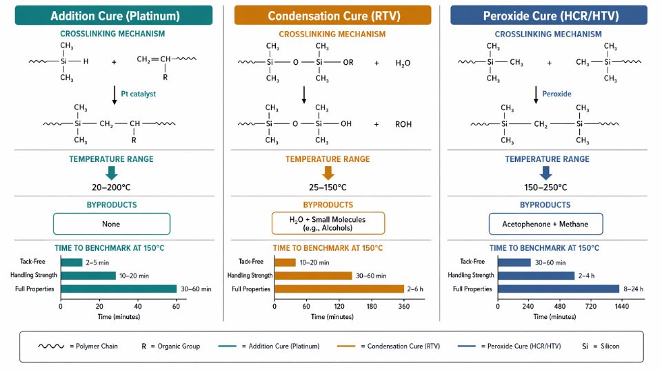
Addition Cure (Platinum Hydrosilylation)
This is the chemistry behind virtually all injection-molded LSR production, and for good reason. The reaction joins silicon-hydride groups (Si–H) on a crosslinker component with vinyl groups pendant on the polymer backbone. Platinum catalyst drives the addition across that double bond, building the three-dimensional network without releasing any byproduct. No shrinkage from volatile loss, no bubbles in tight cross-sections.
At room temperature, a formulated addition-cure system typically holds a pot life of 30 minutes to several hours — the range depends on platinum loading, inhibitor package, and ambient temperature. That window is deliberately engineered. Below roughly 40–50°C, inhibitors suppress the reaction enough to allow mixing, transfer, and injection. Cross the 80°C threshold and cure onset accelerates sharply; at 150–180°C in a heated mold, you’re looking at demolding hardness in seconds to low minutes per millimeter of wall thickness rather than hours.
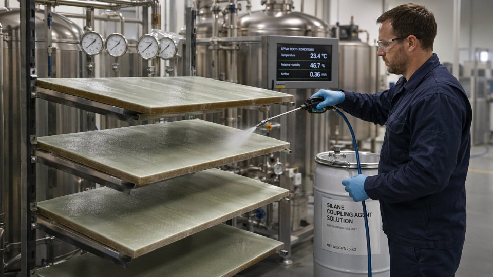
Operational warning: Sulfur compounds, organotin residues, some amine-cured epoxies, and even latex gloves carry platinum poisons. Contact between uncured LSR and any of these — even trace contamination on tooling — produces a permanently soft, tacky surface layer. On a production floor, one contaminated fixture can waste an entire shift’s output before anyone identifies the root cause.
Platinum catalyst poisoning from sulfur or amine contamination causes irreversible surface inhibition in addition-cure LSRTrue
Platinum coordinates preferentially with sulfur and nitrogen ligands, permanently deactivating the catalyst in the affected zone. The bulk material may cure normally while the contact surface remains tacky — a diagnostic signature operators can use to identify contamination sources.
Condensation Cure (RTV-1 and RTV-2 Systems)
Condensation-cure silicones crosslink through moisture-triggered reactions at chain ends, releasing small-molecule byproducts — acetic acid in acetoxy systems, ketoximes in oxime types, alcohols in alkoxy formulations. The chemistry is simpler and cheaper to formulate, which explains its dominance in sealants, encapsulants, and field-applied adhesives.
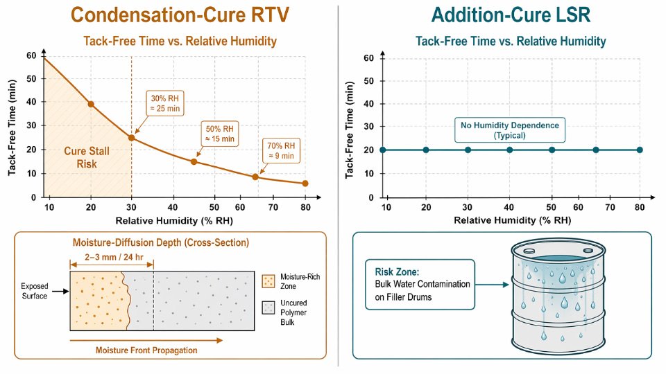
The processing implication that catches engineers off guard is the cure front propagation rate. Moisture must diffuse inward from exposed surfaces, so deep sections cure from outside in at roughly 2–3 mm per 24 hours under standard conditions (23°C, 50% RH). A 12 mm bead may feel firm on the surface after an hour yet remain completely uncured at the center for five or six days. For thick-section bonding — potting a connector, sealing a large flange — this is not a schedule nuisance, it is a structural integrity variable. Elevated humidity accelerates the front; dry warehouse air slows it noticeably.
Peroxide Cure (HCR/HTV)
High-consistency rubber compounds use organic peroxides — typically dicumyl peroxide or DBPH — that decompose thermally at 115–180°C, generating free radicals that abstract hydrogen atoms and drive polymer chain coupling. The elevated temperature requirement is inherent to the mechanism; there is no room-temperature peroxide cure path worth using industrially.
Decomposition leaves residual byproducts — acetophenone, cumyl alcohol, methane — trapped in the part. For most industrial profiles and gaskets this is tolerable. For food-contact or medical-grade components, post-cure at 200°C for 2–4 hours is not optional. It drives residual volatile content from the 1–3% range down below 0.5%, simultaneously improving compression set by a meaningful margin.
How Polymer Architecture Programs Cure Speed
The cure-time figures above aren’t fixed constants — they are outputs of molecular design decisions made during polymer synthesis. Vinyl group density on the backbone controls how many crosslink sites are available; higher vinyl content accelerates network formation but can reduce elongation if taken too far. Molecular weight distribution affects viscosity and the diffusion rate of crosslinker to reactive sites. Cross-linker ratio (Si–H to vinyl molar ratio) sets final network density, which in turn determines hardness, compression set, and the ceiling on achievable cure speed at a given temperature.
Practical Reference: Cure Chemistry vs. Time to Property
| Cure Chemistry | Condition | Tack-Free | Handling Strength | Full Properties |
|---|---|---|---|---|
| Addition (LSR injection) | 23°C | 15–60 min | 2–8 hr | 24–48 hr |
| Addition (LSR injection) | 80°C | 2–8 min | 15–45 min | 2–6 hr |
| Addition (LSR injection) | 150°C | 15–90 sec | 1–5 min | 30 min + post-cure |
| Condensation (RTV-1/2) | 23°C | 15–90 min | 4–12 hr | 24–72 hr+ |
| Condensation (RTV-1/2) | 80°C | 5–20 min | 1–3 hr | 8–24 hr |
| Condensation (RTV-1/2) | 150°C | Not typical | Not typical | N/A |
| Peroxide (HCR/HTV) | 23°C | No cure | No cure | N/A |
| Peroxide (HCR/HTV) | 115–130°C | 3–8 min | 5–15 min | Post-cure required |
| Peroxide (HCR/HTV) | 150–180°C | 1–4 min | 3–10 min | Post-cure required |
Times assume 2–4 mm wall thickness; thicker sections scale roughly linearly for condensation systems and less so for addition and peroxide due to thermal lag in the mold. Humidity below 30% RH can extend condensation cure times by 40–80%.
Critical Variables That Accelerate or Delay LSR Cure in Real Production Conditions
Datasheet cure times are measured under controlled lab conditions. On a real production floor, a dozen variables pull cure time in both directions simultaneously. Knowing which lever is active — and by how much — is what separates a process engineer from a line operator reading a spec sheet.
Temperature and the Arrhenius Effect on Hydrosilylation
Platinum-catalyzed addition cure follows Arrhenius kinetics closely enough that a practical rule holds: every 10°C increase in mold or ambient temperature roughly halves cure time. Starting from a 23°C baseline where tack-free surface cure might take 30–60 minutes, moving to a 120°C mold drops equivalent cure to 2–4 minutes, and a 180°C mold can push demolding time below 45 seconds for thin-wall parts. The actual numbers depend on catalyst loading, inhibitor package, and part geometry — treat these as order-of-magnitude targets, not process set points. Setting mold temperature above 210°C without confirming thermal stability with your material supplier risks surface degradation before the core reaches cure.
Humidity: Opposite Effects Depending on Cure Chemistry
In condensation-cure RTV systems, atmospheric moisture is a reactant. Higher relative humidity — above 50–60% RH — accelerates surface skin formation, which is why these products cure measurably faster in summer production environments than in climate-controlled winter facilities. Below 30% RH, skin formation can stall, leaving parts vulnerable to handling damage for extended periods.
Addition-cure LSR is largely insensitive to ambient humidity under normal conditions. The risk emerges differently: if bulk water contamination enters the catalyst component through condensation on cold filler drums or improperly sealed containers, it can partially deactivate the platinum complex and extend gel time unpredictably. This is an intermittent defect that tends to be misdiagnosed as a mixing problem.
Section Thickness and Heat Transfer Limitations
A 1 mm gasket in a heated mold reaches cure temperature within seconds. A 25 mm potting block is a thermal insulation problem: the outer surface reaches mold temperature while the core lags by a margin governed by Fourier heat conduction — and LSR’s thermal conductivity is low, typically in the range of 0.2–0.3 W/m·K. As a practical scaling guideline, add roughly 15–30 seconds of additional dwell time per additional millimeter of wall thickness beyond the first 2 mm, adjusted upward for filled or pigmented grades with even lower conductivity. Skipping this calculation produces parts that appear demolded-ready but contain an under-cured core that relaxes dimensionally under load.
Catalyst Loading and Inhibitor Balance
Increasing platinum ppm speeds cure onset and reduces pot life proportionally. Inhibitor packages — thermal inhibitors, UV stabilizers, or chemical inhibitors like vinyl-functional siloxanes — work by raising the activation threshold, giving longer pot life without meaningfully changing final crosslink density or mechanical properties once full cure is reached. This is a formulation lever, not a fix for a process problem. Doubling platinum to compensate for low mold temperature while leaving inhibitor levels unchanged will produce pot-life failures at the static mixer or dispensing head.
Substrate and Mold Contamination as Catalyst Poisons
Sulfur, tin, nitrogen, and phosphorus compounds are potent platinum catalyst poisons. Even trace contamination — residual mold release agents containing organotin, rubber gloves with sulfur-based accelerators, certain cutting fluids — can extend cure from minutes to complete inhibition in a localized contact zone. The failure mode is a tacky, uncured layer exactly at the part surface while the bulk cures normally. Industrial contamination sources include shared molds previously used for peroxide-cure HCR, amine-based release agents, and polysulfide sealants applied elsewhere in the facility.
Sulfur-containing mold release agents can permanently inhibit platinum catalyst at the part surface even at sub-ppm contamination levels.True
Platinum catalyst poisoning by sulfur compounds is well-established in hydrosilylation chemistry; sulfur coordinates strongly to platinum, blocking catalytic sites and preventing crosslink initiation at the contaminated interface.
Mixing Ratio Accuracy
Two-component addition LSR systems are typically formulated at a 1:1 A:B ratio, but some grades run at 10:1 or custom ratios. A deviation of ±5% from target ratio leaves stoichiometrically unbalanced Si-H or vinyl groups in the network. The result is residual surface tack that no amount of additional heat will fully resolve, because the missing crosslinks simply are not there to form. Gravimetric dispensing with load-cell verification catches drift that volumetric gear pumps — subject to wear and viscosity-change errors — will miss entirely.
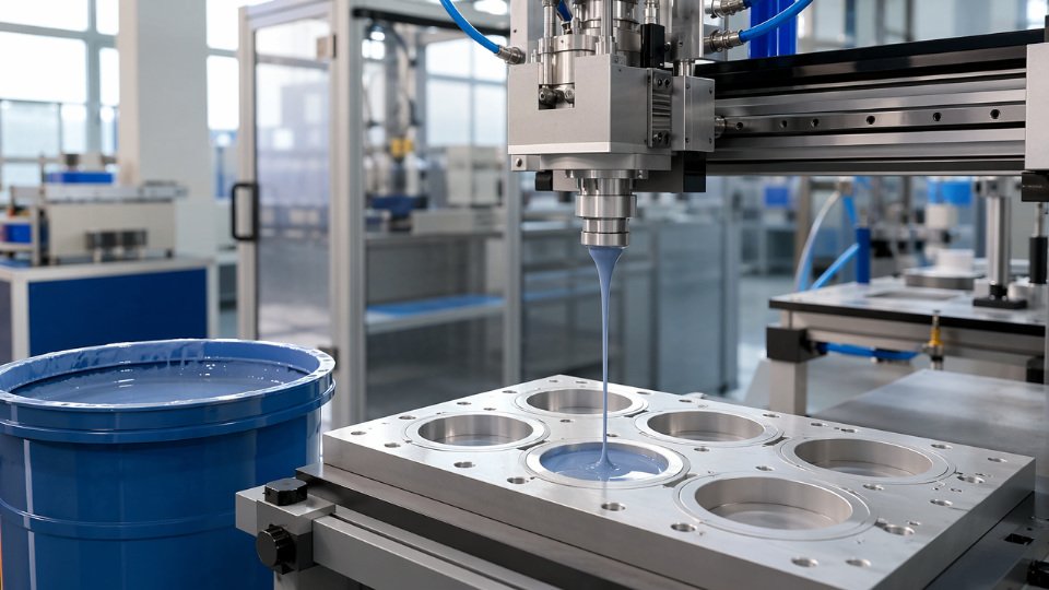
Ambient Pressure in Vacuum and Autoclave Processing
For condensation systems, reduced pressure accelerates outgassing of the acetic acid, oxime, or alcohol byproducts that are actually consumed in the crosslinking reaction. Pulling a vacuum prematurely can strip reactive byproducts before cure completes, leaving a porous, under-cured part. In vacuum casting of addition LSR, the primary concern is dissolved air removal before gelation — pressure is less critical to the chemistry itself, but reintroducing atmosphere too early collapses voids before the network stabilizes. Autoclave processing adds the variable of elevated pressure modifying effective boiling points of trace volatiles, which matters most during post-cure scheduling.
Room-Temperature Cure LSR (RTV-1 and RTV-2): Realistic Timeline Benchmarks by Application
RTV systems cure without heat, which makes them indispensable for field sealing, potting of installed assemblies, and flexible mold-making — but that convenience comes with timelines that vary widely depending on chemistry, geometry, and environment. Treating datasheet figures as fixed guarantees problems. What follows are realistic ranges, tied to the variables that actually move them.
RTV-1 Sealants: Tack-Free Is Not Done
Single-component RTV-1 systems cure by absorbing atmospheric moisture, so cure rate is a direct function of relative humidity and temperature. At 23°C and 50% RH — the standard test condition — expect tack-free surface in 15–60 minutes depending on formulation viscosity and film thickness. The through-cure rate for most acetoxy and oxime RTV-1 products follows a practical rule: roughly 3 mm of depth per 24 hours under standard conditions. A flange bead that is 9 mm wide will not reach full cohesive strength at its core for approximately 72 hours.
In cold-climate field applications — think outdoor junction box sealing at 5°C and 30% RH in winter — that 3 mm/day rate can slow to 1–1.5 mm/day. Bolting down a sealed joint after only a surface cure is a documented failure mode: the soft uncured core deforms under clamp load, never recovers proper geometry, and the joint leaks under thermal cycling. Full adhesion strength, meaning the figure quoted on a datasheet for lap-shear or peel tests, typically requires 5–7 days at standard conditions. Plan quality hold times accordingly before pressure-testing sealed assemblies.
RTV-2 Encapsulants: Gel Point ≠ Safe Handling
Two-part RTV-2 pourable systems reach gel point — the moment the mixed liquid stops flowing and begins to hold shape — somewhere between 30 and 120 minutes depending on catalyst loading, accelerator presence, and ambient temperature. Demold time for typical 10–50 Shore A encapsulant grades runs 4–16 hours. The shorter end applies to accelerated low-Shore formulations; the longer end applies to very soft, high-elongation grades that need more time to develop handling integrity.
The critical operational mistake is equating gel point with safe handling time for electronics. A potted PCB assembly that gels in 45 minutes may still transmit enough stress during early demolding to crack solder joints on BGA components or damage fine-wire bonds. Dielectric properties — volume resistivity and dielectric strength — continue stabilizing for 24–48 hours after apparent surface cure, particularly in high-humidity environments.
RTV-2 encapsulants reach full electrical performance immediately after gelationFalse
Dielectric properties in RTV-2 systems continue to develop for 24–48 hours post-gel as crosslinking density increases and any residual byproducts dissipate. Testing to IPC or equivalent electrical standards before this window closes will produce non-representative results.
RTV-2 Mold-Making Grades: Three Distinct Cure Milestones
Silicone tooling applications involve three operationally distinct milestones, not one. Pattern extraction — pulling out the master without distorting the cavity — is typically safe at 6–12 hours for standard mold-making grades at 25°C. Dimensional stability sufficient to hold casting pressure from polyurethane or epoxy resins requires a full 24-hour cure; rushing this produces mold growth and distorted part dimensions. Full tear resistance, which determines how many pulls the tool survives before edge tearing begins, requires 72 hours. Demold at 8 hours and cast at 10 hours and you will likely get good first articles — then watch the parting-line edges degrade 30–50% faster than expected over the tool’s service life.
Conformal Coatings: Thin Films, Fast Surface, Slow Dielectric
At 50–200 µm application thickness, RTV-2 conformal coatings reach tack-free in 10–20 minutes at room temperature. A forced-air oven at 80°C cuts that to roughly 5 minutes and is standard practice in high-throughput PCB coating lines. What the line timer does not capture is dielectric property stabilization — full volume resistivity values typically need 24 hours at room temperature or 1–2 hours at 80°C before the coated assembly should go into any high-voltage functional test.
Formulation Selection and Shelf Life Interactions
SiliconChemicals’ RTV-2 bases span a range of polymer molecular weights and filler loadings that directly govern the cure speed versus flexibility trade-off. Higher-molecular-weight polymers yield better tear resistance and elongation but cure more slowly; higher filler loading improves dimensional stability in mold grades but can extend demold times by 20–40% compared to unfilled analogues. Accelerated-cure grades — formulated for production environments where a 4-hour mold cycle is unacceptable — typically sacrifice some pot life, running 15–30 minutes versus 60–90 minutes for extended-pot-life grades. Match the grade to the process, not the other way around.
One variable that rarely appears on datasheets but matters operationally: catalyst age. RTV-2 platinum catalysts and tin condensation catalysts both lose activity over time, particularly if stored above 25°C or exposed to contamination from amine vapors or sulfur-containing materials. A drum of catalyst component that is 10–12 months old and has seen variable storage temperatures may extend gel time by 50–100% relative to datasheet values. Working from fresh material — and rotating stock on a strict FIFO basis — is the single most reliable way to hit consistent cure times across production batches.
Injection-Molded and Compression-Molded LSR: Cure Cycles, Cycle Times, and Demolding Criteria
In high-volume LSR molding, cure time is not a quality metric in isolation — it is the dominant variable in your cost-per-part calculation. Shaving 10 seconds off a 60-second cycle on an 8-cavity tool running three shifts changes the economics of a program. Getting that reduction wrong costs you scrap, torn parts, and torn-out insert threads.
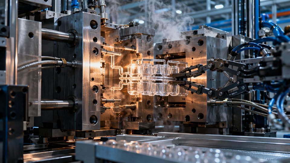
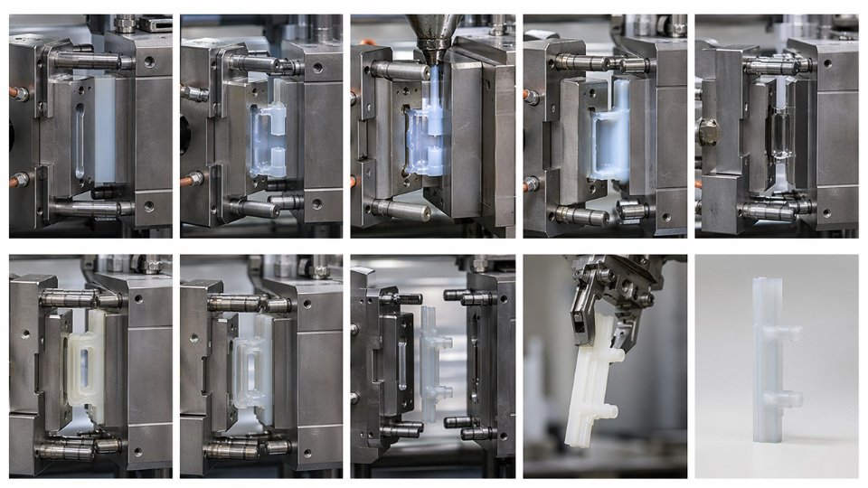
The Anatomy of an Injection Mold Cycle
A standard LSR injection cycle breaks into three distinct phases. Fill — typically 2–10 seconds depending on part volume, runner geometry, and material viscosity — is followed by cure dwell under heat and pressure, then demolding and reset. The dwell phase is where most optimization effort belongs.
At mold temperatures of 170–200°C, cure dwell for 1–4 mm wall sections runs roughly 15–90 seconds. The lower bound applies to thin, simple geometries with fast-curing addition-cure compounds; the upper bound reflects thicker cross-sections, cooler mold settings, or base polymers with higher viscosity that slow heat penetration. Wall thickness is the dominant variable, but it is not the only one — runner volume matters too, because gating that is significantly thicker than the part wall cures last and sets your minimum cycle.
Mold temperature uniformity deserves more attention than it typically gets on the plant floor. A ±3°C differential across cavities sounds small. In practice, the cooler cavities will be undercured at demolding, producing parts that tear during ejection or deform under ejector pin load. Consistent waterline design, manifold balancing, and regular thermocouple calibration are not optional in a well-run LSR cell.
Demolding Hardness: The Practical Go/No-Go Criterion
You cannot measure crosslink density at the press. What you can measure — or at least assess — is surface hardness and part integrity at ejection. Targeting 80–90% of the compound’s final Shore A hardness at demolding is a workable rule. Full property development continues 2–4 hours post-mold at room temperature as residual crosslinking completes, so demolding at 75% risks dimensional instability in tight-tolerance components.
Thin membranes in the 0.3–0.5 mm range, common in respiratory masks and valve diaphragms, can reach demolding hardness in 10–15 seconds at 200°C. Multi-cavity medical components with thick cold-runner gating — typical gating lands of 3–5 mm — often require 45–75 seconds even when cavity walls are thin, because the gating controls your actual minimum cure time.
LSR parts reach 100% of their final mechanical properties immediately at demolding from a heated mold.False
Injection-molded LSR typically achieves 80–90% of final Shore A hardness at demolding; full property development, including compression set and tear strength, continues for 2–4 hours at room temperature as residual addition-cure crosslinking completes.
Compression and Transfer Molding: Slower by Design
Compression and transfer molding of HCR compounds operates at lower mold temperatures — 150–170°C is typical — with correspondingly longer cycle times of 3–8 minutes. The physics are straightforward: lower temperature means slower activation of the peroxide or platinum catalyst, which means longer dwell required to reach demolding hardness. The payoff is lower tooling cost and the ability to mold parts with complex inserts or geometries that injection tooling cannot accommodate cleanly. The liability is flash: longer dwell at lower pressure gives material more time to migrate into parting-line gaps, so flash formation is a chronic compression-mold problem that tighter clamp tonnage only partially solves.
Cold Runner vs. Hot Runner: A Real Trade-off
Cold runner tooling keeps the entire runner system at the same elevated temperature as the cavity, meaning runner material cures with every shot and becomes waste — a meaningful cost factor on platinum-catalyzed compounds. Hot runner (cold deck) systems maintain the runner manifold at 5–15°C to preserve pot life while cavities run at full cure temperature. The efficiency gain is real. The risk is equally real: if manifold temperature control drifts upward, you initiate cure in the runner and face plugging, inconsistent fill, or cross-contamination between shots.
Cycle Optimization: What Actually Moves the Needle
Ranked by ease of implementation and magnitude of impact:
| Lever | Implementation Difficulty | Typical Cycle Reduction | Key Risk |
|---|---|---|---|
| Mold temperature increase (+10°C) | Low | 15–25% | Flash, scorching in thin sections |
| Catalyst loading increase | Medium | 10–20% | Reduced pot life, scrap on delays |
| Crosslinker ratio tuning | Medium | 5–15% | Over-crosslinking reduces elongation |
| Tool redesign (runner geometry) | High | 20–40% | Tooling cost, validation time |
Raising mold temperature is the fastest lever. Each 10°C increase roughly halves the activation energy barrier for platinum-catalyzed addition cure, though the practical ceiling is bounded by flash risk in thin sections and by compound scorching in restricted flow areas.
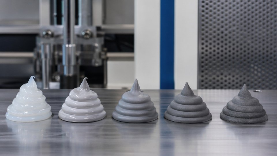
Viscosity Grade and Its Effect on Achievable Cycle Times
LSR base polymer viscosity — ranging from around 10,000 mPa·s in fast-flow grades up to 800,000 mPa·s in high-consistency types — affects both fill behavior and cure kinetics. Lower-viscosity grades fill faster and transfer heat more readily from the mold surface, which can support shorter cure dwells, particularly in thin-wall parts. Higher-viscosity grades retain more cross-section temperature differential during fill, meaning the core takes longer to reach cure temperature than the surface. For multi-cavity tooling running 0.8–2 mm medical or electronics components, a 50,000–200,000 mPa·s grade typically balances flow, cycle time, and mechanical property requirements. Moving to a lower-viscosity grade purely to shorten cycle time without revisiting catalyst loading and crosslinker ratio is a common optimization error that produces parts with acceptable hardness but degraded compression set.
Post-Cure Protocols: When Secondary Heat Treatment Is Mandatory vs. Optional
Demolding a part and calling it finished is one of the more expensive assumptions a process engineer can make with LSR. The mold cure cycle brings the material to handling hardness — it does not complete the polymer network, and it leaves behind chemistry that will cause problems in service if you ship the part as-is.
What Post-Cure Actually Does to the Material
Four distinct things happen inside the oven during post-cure, and they matter independently of each other.
First, residual crosslinking reactions that stalled at mold temperature — because cure kinetics slow as conversion approaches 100% — are driven to practical completion. Second, low-molecular-weight cyclic siloxanes (predominantly D3 through D6 fractions) that remain trapped in the matrix volatilize and diffuse out. Fresh-molded engineering-grade LSR typically carries 1–3% volatile content by weight; a 200°C circulating-air post-cure for 2–4 hours brings that to below 0.5%, depending on part cross-section and oven airflow. Third, for peroxide-cured systems specifically, decomposition byproducts — primarily acetophenone and cumyl alcohol from dicumyl peroxide — need to be driven off. These byproducts cause odor complaints and are a migration concern in any food or medical application. Addition-cure LSR has a cleaner post-cure obligation, but the cyclic siloxane removal still applies. Fourth, molded-in stress from rapid cavity pressurization and thermal gradients relaxes, which matters for dimensional stability in tight-tolerance components like connector seals or catheter components.
Industry Requirements That Make Post-Cure Non-Negotiable
For medical device applications, ISO 10993 biocompatibility testing is conducted on post-cured samples by convention. If your production parts skip that step, the tested sample and the shipped part are not the same material state — a finding that will surface during an FDA audit or notified body review. FDA 21 CFR food-contact compliance and EU Regulation 10/2011 both set migration limits for cyclic siloxanes; meeting those limits without post-cure is essentially impossible for standard LSR formulations at typical shot weights. Automotive customers operating under IATF 16949 frameworks routinely embed post-cure as a documented control in the PFMEA and control plan, meaning your skip-lot deviation needs engineering approval that will almost certainly be denied.
Post-cure is required to meet FDA 21 CFR and EU 10/2011 cyclic siloxane migration limits for food-contact LSR partsTrue
Standard LSR formulations contain 1–3% low-molecular-weight cyclic siloxanes post-mold; regulatory migration thresholds for D4/D5/D6 cannot reliably be met without the volatilization step that post-cure provides.
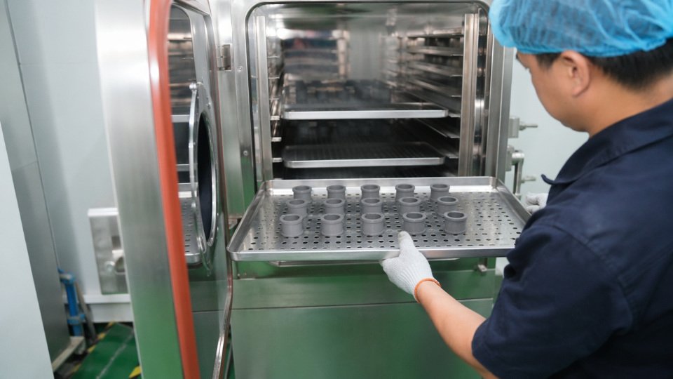
Running the Post-Cure Correctly
The standard protocol — 200°C for 2–4 hours in a circulating-air oven — is straightforward on paper. In practice, oven loading density kills it. Pack trays too densely, or use solid sheet trays that block vertical airflow, and parts in the interior of the stack run 20–40°C cooler than the setpoint. That translates directly to incomplete volatile removal. Use wire mesh or perforated trays, maintain a minimum 25–30 mm gap between part layers, and validate oven temperature uniformity with thermocouples at the cold spots before releasing the process. Thick cross-sections — above roughly 6 mm — may need the upper end of the time range, or a staged ramp, to avoid surface re-condensation of volatiles that then reabsorb into the part.
Measurable Property Changes You Should Be Seeing
Post-cure typically moves compression set from the 25–35% range down to 10–18% for engineering-grade formulations. That difference is the gap between a sealing application that passes qualification and one that leaks at 18 months. Elongation and tear strength stabilize rather than increase significantly — the main effect is reduced batch-to-batch scatter. Dielectric loss tangent drops measurably, relevant for high-frequency insulation and cable accessory applications.
When You Can Skip It
General-purpose RTV sealants in construction joints, non-structural gap fillers, and vibration damping pads in non-food, non-medical environments generally don’t need post-cure as a production step. Cyclic siloxane migration into a concrete expansion joint is not a regulatory event. For condensation-cure RTV used in structural glazing, a lighter version of post-cure logic applies: airing parts at 50–60°C for several hours accelerates byproduct volatilization (acetic acid or oxime, depending on the system) and improves adhesion cohesion at the substrate interface.
Releasing Parts After Post-Cure
Weight loss measurement before and after post-cure is the most direct proxy for volatile removal — aim for a loss that moves total volatile content below your target threshold, typically 0.5% or the limit specified in your customer’s material spec. Confirm Shore A hardness, which should be stable or marginally higher than as-molded. For sealing applications, run 100% elongation set as a production release check rather than relying on the cure schedule alone; an oven that’s drifted 15°C low on thermocouple calibration will pass a schedule check and fail a properties check.
How to Measure and Verify LSR Cure State: Tools and In-Process Quality Methods
Elapsed time and a fingernail scratch tell you almost nothing about whether a silicone part is actually cured. Temperature fluctuations, batch-to-batch inhibitor variation, and cross-section geometry all shift actual cure state away from the nominal cycle on a process sheet. What follows are the methods that quality engineers and process technicians actually use — from the press-side floor to the analytical lab — ranked roughly by cost and complexity.
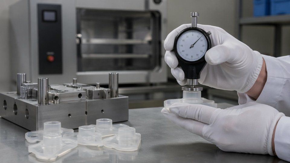
Shore A Durometer: The Fastest Floor Check
A Shore A durometer is the default cure-verification tool in most molding operations, and it works well when used correctly. The key discipline is stabilization time: measure too soon after demolding and the reading is meaningfully lower than the true plateau value because silicone continues to crosslink and the elastomer is still warm. A minimum 15-minute rest at ambient conditions before measurement is a practical floor standard; parts that have just come off a 180°C tool need longer, closer to 30 minutes, to reach thermal equilibrium.
Correlating Shore A to cure completion requires establishing a plateau value for each compound during process qualification. When consecutive readings taken 10 minutes apart differ by less than 1 Shore A unit, the surface cure has stabilized. One operational limitation: for ultra-soft grades below 10 Shore A — common in wearable and medical cushioning applications — Shore A resolution is too coarse, and Shore 00 or micro-indentation methods become necessary.
Rheometry (MDR/RPA): Building the Cure Spec from Lab Data
Moving die rheometer (MDR) or rubber process analyzer (RPA) tests generate the torque-versus-time curves that define T10 and T90 — the times to reach 10% and 90% of maximum developed torque, respectively. These parameters are how a lab translates cure chemistry into production cycle time specs. T90 is not a demolding criterion by itself; most molding operations target 90–95% of maximum torque to balance dimensional stability with acceptable cycle time.
Peroxide-cured systems require specific attention to the marching modulus phenomenon, where torque continues rising past the apparent plateau for an extended period. Treating an early-plateau T90 as full cure in these systems leads to parts that continue hardening in service — a particular concern for dimensional-tolerance components.
MDR T90 values measured at mold temperature directly predict safe demolding time for injection-molded LSRTrue
MDR test conditions match actual mold temperature, so T90 at 170–190°C is a validated predictor of in-mold crosslink density at demolding, provided the compound and cure system are consistent between lab sample and production batch.
DSC: Quantifying Residual Cure for Validation Work
Differential scanning calorimetry measures the residual exotherm in a partially or fully cured sample. For first-article inspection and medical device process validation, DSC gives a percentage cure completion figure rather than a pass/fail hardness reading. Acceptable residual exotherm thresholds vary by application but are typically below 5 J/g for medical-grade parts that will undergo post-cure.
Extractables and Volatiles: The Compliance Test
Food-contact and medical grades must meet extractables limits — most commonly below 0.5% cyclic siloxane content by weight. Soxhlet extraction in isopropanol or headspace GC-MS are the standard methods. These tests belong in the post-cure release protocol, not as a substitute for it. Discovering out-of-spec extractables after shipment is an expensive correction; building the test into the lot-release sequence prevents it.
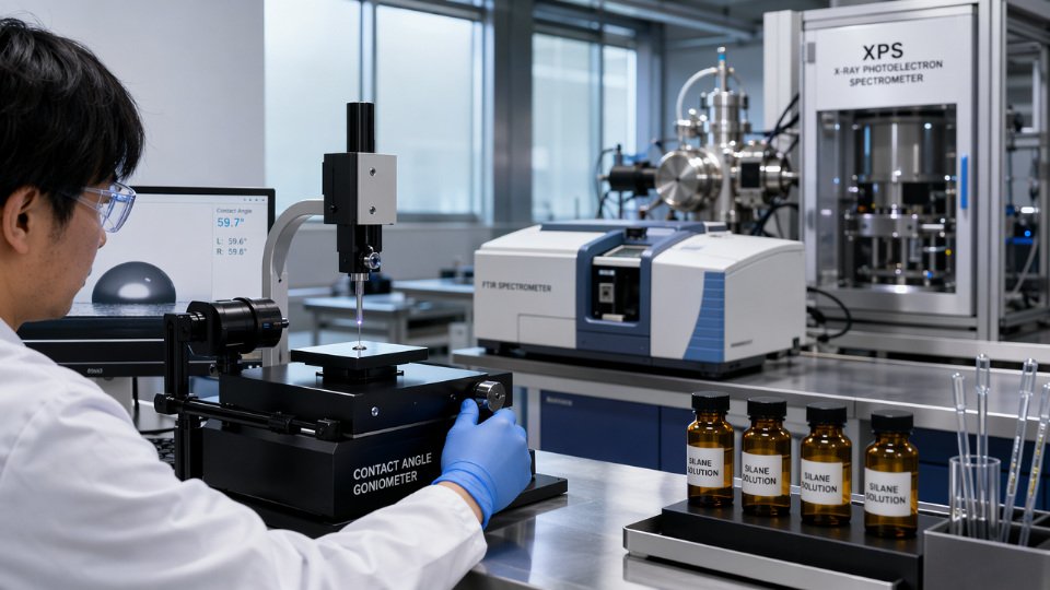
ATR-FTIR: Direct Chemistry at the Surface
ATR-FTIR monitoring of the Si-H absorption band near 2150 cm⁻¹ gives a direct read on hydrosilylation reaction completeness in addition-cure systems. As crosslinking proceeds, the Si-H peak area decreases proportionally. This is particularly useful during process development or inhibition troubleshooting, where you need to distinguish between slow cure and no cure.
Peel Adhesion for RTV Sealant Applications
For RTV sealants used in bonding and sealing applications, a 180° peel or tensile pull-off test on the actual production substrate is more meaningful than any time-based hold period. Adhesion development lags surface tack-off by hours, and substrate type, surface preparation quality, and primer selection all affect the actual bond-strength curve. A functional adhesion test on representative coupons — run in parallel with production assemblies — gives a release criterion tied to performance rather than the clock.
A Practical Dual-Criterion Release Protocol
SiliconChemicals’ technical service team recommends a cost-effective two-checkpoint approach for most production environments: a Shore A durometer check against the qualified plateau value after adequate stabilization time, combined with a post-cure weight-loss measurement to confirm volatile reduction below the application threshold. Together, these two checks catch both under-cured parts and inadequately post-cured parts without requiring lab instrumentation at every lot. Reserve DSC and extractables testing for initial process qualification, regulatory submissions, and any lot where the cure cycle deviated from the validated parameters.
Troubleshooting Incomplete Cure, Surface Tack, and Inhibition in LSR Processes
Cure failures rarely announce themselves cleanly. A part comes out tacky, a thick seal feels soft in the core, a bonded insert delaminates on the first flex test. Each symptom points to a different root cause, and misdiagnosing one costs you material, press time, and often a full mold strip-down.
Persistent Surface Tack After Specified Cure Time
Work through this systematically before adjusting temperatures or extending cycle times blindly. The most common causes, in rough order of frequency:
- Catalyst poison contamination — any contact with sulfur, tin, phosphorus, or nitrogen compounds before or during molding will inhibit platinum catalyst activity at the surface or throughout
- Off-ratio mixing — Part A:Part B ratio drifting beyond ±2% of the specified 1:1 (or 10:1, depending on formulation) produces stoichiometric imbalance; static mixer wear or pump slippage are common causes in high-throughput machines
- Mold or oven temperature below spec — thermocouple placement matters; a sensor mounted in the platen versus the cavity face can show a 15–25°C discrepancy depending on mold mass and thermal insulation quality
- Expired or degraded material — platinum-addition LSR stored beyond 12 months, or exposed to temperatures above 30°C during transit, shows reduced catalyst activity; shelf-life dates on drum labels are not conservative estimates
- Section thickness underestimated — a 12 mm cross-section cured on a cycle calibrated for 4 mm will have an undercured core even if the surface passes touch-feel
Platinum Poisoning: Identification and Mold Decontamination
Platinum poisoning is the single most disruptive inhibition failure in injection molding operations. Sulfur is the most aggressive inhibitor — it migrates from latex or natural rubber gloves, gaskets, and handling tools. Tin compounds off-gas from PVC conveyor belts or tin-cure RTV used elsewhere in the facility. Cutting fluids containing amine or nitrogen-based corrosion inhibitors can contaminate mold cavities during maintenance.
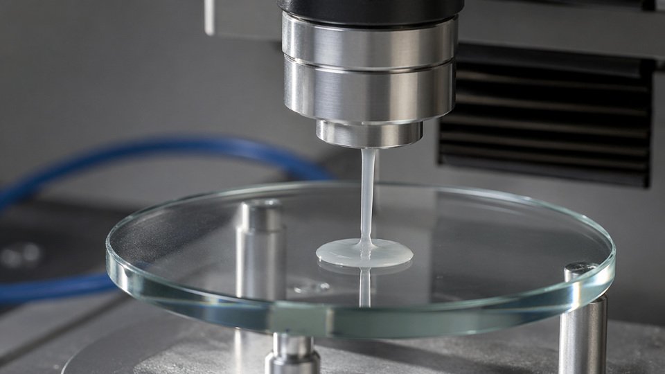
The standard field test: cure a small volume of your LSR against a clean glass plate at process temperature. Full cure on glass rules out material or ratio issues and confirms the contamination is mold-resident or environment-resident.
Sulfur from a single contact with a natural-rubber glove can inhibit platinum catalyst across an entire mold cavity surfaceTrue
Platinum catalyst is active at parts-per-million concentrations, meaning trace sulfur from rubber gloves is sufficient to form stable platinum-sulfide complexes that permanently deactivate the catalyst at the contact surface. This is well-documented in silicone processing literature and consistent with inhibition chemistry.
Mold decontamination requires more than a solvent wipe. Affected cavities typically need mechanical abrasion with fine abrasive media or dedicated silicone mold cleaner, followed by a sacrificial cure cycle with expendable LSR that is discarded. Plasma treatment is effective for precision molds but rarely practical on the production floor without specialist equipment.
Soft Core With Cured Surface
This pattern almost always means heat hasn’t penetrated adequately — or catalyst activity is marginal. For sections thicker than 8–10 mm, heat transfer through LSR (thermal conductivity roughly 0.2–0.3 W/m·K, depending on filler content) limits center temperature rise significantly. Corrective actions: reduce shot size and increase cure time before scaling back up, implement a temperature ramp rather than step-change profile, and verify static mixer condition — a worn or partially blocked mixer produces streaked, non-homogeneous mix that shows variable cure across a cross-section.
Delamination and Adhesion Failure at Interfaces
Distinguish quickly between cure-related and primer-related failures. If LSR peels cleanly from a substrate with no transfer, the primer either wasn’t applied or wasn’t activated. If LSR cohesively tears but adhesion is low, suspect fast cure speed — rapid crosslinking reduces wetting time at the substrate interface before the network locks. Slowing cure by 10–15% through a modest temperature reduction, or switching to a slower-reacting grade, often resolves borderline bond failures on difficult substrates like unfilled polyamide or polypropylene.
Yellowing and Discoloration During Cure
Peroxide-cured LSR produces organic decomposition byproducts that yellow above 180°C and in confined airflow. For optical or aesthetic grades, addition-cure is almost always the right choice. In addition-cure systems, yellowing above 210–220°C indicates onset of platinum-catalyzed thermal reversion — the same catalyst that crosslinked the network begins facilitating backbone rearrangement and oxidation. Optical-grade LSR should generally not exceed 190°C in production cure cycles.
Marching Modulus and Over-Cure in Thin Sections
Prolonged exposure above 220°C shifts the balance from crosslinking to chain scission. You’ll see this as unexpected softening, surface crazing, or loss of tensile strength in thin-walled parts (wall thickness under 1.5 mm is particularly vulnerable). If hardness measurements are trending upward over successive cycles then suddenly dropping — that’s the classical marching-modulus signature followed by over-cure degradation. Tighten your temperature windows and audit oven dwell time independently of cycle time.
Documentation and Escalation Protocol
When a cure failure occurs, capture these variables immediately before any process changes: mold temperature at multiple points, mix ratio confirmed by gravimetric check, batch numbers for both Part A and Part B, storage conditions and age, any recent maintenance or cleaning on the mold or equipment, and a sample of the failed part sealed in a clean polyethylene bag. This log is what makes the difference between a productive conversation with a formulation team and a dead-end troubleshooting call. If the failure is reproducible and root cause remains unclear after working through the checklist above, SiliconChemicals’ technical application engineers can perform inhibition testing, catalyst activity titration, and rheological analysis on returned samples to diagnose formulation-level issues that field testing cannot resolve.
Frequently Asked Questions About LSR Cure and Drying Time
Can I speed up LSR cure at room temperature by adding more catalyst?
Not in any useful, linear way. Platinum catalyst loading in addition-cure RTV-2 systems is formulated to balance pot life against through-cure rate. Doubling the catalyst beyond the supplier’s recommended ratio — typically 1–5 parts per hundred resin depending on the system — will shorten the initial gel time but creates an uneven cure front: the surface locks up while the interior is still mobile. The result is internal stress, reduced elongation at break, and in pigmented compounds, a visible color shift toward yellow or amber. For condensation RTV-1 systems, catalyst excess accelerates surface skin formation but actually traps moisture pathways, slowing through-cure in thick sections. Use temperature before you touch catalyst ratios.
How long before an LSR sealant can be submerged in water or exposed to chemicals?
Tack-free time and chemical resistance are not the same milestone. An RTV-1 sealant may skin over in 15–45 minutes at 23°C/50% RH, but the siloxane network continues crosslinking for days. Full chemical resistance — meaning resistance to hydrolysis, fuel splash, and cleaning agents — typically requires 7 days of ambient cure at standard conditions. Submersion before that point risks swelling, bond-line softening, and adhesion loss at the substrate interface. For aggressive chemical environments such as brake fluid or concentrated acids, request full through-cure confirmation by Shore A durometer before the assembly goes into service.
Does LSR cure faster in summer humidity vs. winter dryness?
Only if you’re running a condensation-cure (moisture-cure) system. RTV-1 condensation products crosslink by reacting with atmospheric moisture, so at 70–80% RH in summer you can expect tack-free times 30–50% shorter than at 20–30% RH in a dry winter facility — a difference that directly affects production scheduling and fixture hold times. Addition-cure RTV-2 and injection-molded LSR systems are essentially humidity-independent; their crosslinking kinetics are driven by temperature and catalyst concentration, not ambient moisture.
Humidity has no meaningful effect on addition-cure platinum-catalyzed LSR cure rateTrue
Platinum-catalyzed hydrosilylation proceeds via Si-H and vinyl group reaction; water is not a reagent or catalyst in this mechanism, so ambient humidity does not accelerate or retard cure
What is the shelf life of uncured LSR, and does it affect cure time?
Platinum catalyst activity degrades over time, particularly above 25°C or in the presence of sulfur, nitrogen, or tin contaminants from packaging or storage environments. Most two-part addition-cure LSR compounds carry a working life of 12–18 months from manufacture date when stored sealed at or below 25°C in the dark. As material approaches the end of shelf life, you may see extended gel times, incomplete cure at standard press parameters, and increased residual tack — all before visible signs of degradation appear. First-in, first-out inventory management is not optional; it’s a yield protection strategy.
Can LSR be cured with UV light instead of heat?
Yes, for specific formulations. UV-addition cure systems use photoinitiator-activated hydrosilylation rather than thermal activation. These are niche but real products used in electronics encapsulants, optical bonding, and thin-film medical device coatings where heat above 60–80°C would damage substrates or pre-assembled electronics. Cure depth is the practical constraint — UV penetration drops sharply beyond 2–4 mm depending on filler loading and pigmentation, so UV cure is limited to thin sections or optically clear compounds.
How do I know if my LSR is fully cured without lab equipment?
Three practical field methods, in order of reliability. First, fingernail indentation on a non-cosmetic surface: fully cured material rebounds without any mark at the rated Shore A hardness. Second, dimensional stability: measure a critical feature against drawing tolerance; under-cured parts show measurable shrink drift over 24 hours. Third, for peroxide-cure systems only, a residual odor test — byproduct decomposition products have a distinctive sharp smell that dissipates as cure completes. None of these replace a durometer or compression-set test for specification sign-off, but they will catch gross under-cure on the floor before parts ship.
What happens if LSR is removed from the mold before it is fully cured?
Warpage is the most immediate consequence, because the still-plastic network distorts under its own weight or handling stress. More problematic: residual stress locked into the geometry propagates surface microcracks during subsequent post-cure or assembly. Thin-walled parts — under 1 mm — are occasionally salvageable by returning them flat to a secondary cure fixture quickly, but complex geometries rarely recover without dimensional nonconformance. The cost of a 30-second extended press cycle is always lower than the scrap cost of premature demolding.
Is post-cure always required for food-contact LSR parts?
Not always legally required, but the risk calculus almost always justifies it. Post-cure at 200°C for 2–4 hours drives residual volatile siloxanes — primarily cyclic D4 and D5 — below levels targeted by EU Regulation 10/2011 and FDA 21 CFR thresholds. Without post-cure, residual volatile content typically runs 1–3% by weight; post-cure brings this below 0.5%. SiliconChemicals’ standard recommendation for any food-contact, infant-product, or implant-adjacent application is to treat post-cure as mandatory unless migration testing on the specific compound and geometry has already demonstrated compliance. Testing costs less than a recall.
Selecting the Right LSR Grade and Cure System for Your Application’s Time Constraints
Every section before this one has built a technical foundation. Now the practical question is: given your specific geometry, equipment, regulatory context, and throughput target, which cure chemistry and which grade actually fits? Getting this wrong costs real money — either in cycle time waste, failed post-cure audits, or scrapped parts from inhibition events that a better-matched formulation would have avoided.
Application-Type Decision Matrix
Start with what you’re making and how fast you need it done, then work backward to chemistry.
| Application | Acceptable Cure Window | Heat Available? | Recommended Chemistry |
|---|---|---|---|
| Injection-molded seals, valves | 30 s – 3 min cycle | Yes (150–200°C mold) | Addition-cure HTV/LSR, platinum-catalyzed |
| Structural encapsulation, potting | 30 min – 24 hr | Sometimes | RTV-2 addition or condensation, depending on substrate sensitivity |
| Field sealing, maintenance repair | 15 min tack-free, 24–72 hr full cure | No | RTV-1 moisture-cure |
| Mold-making, prototype tooling | 2–8 hr working time needed | No | RTV-2 condensation, extended pot life grades |
| Medical device components | Fast cycle + post-cure validation | Yes | Low-cyclic addition LSR with documented volatile profile |
| Food-contact gaskets | Fast cycle + extraction testing | Yes | Platinum addition, low-volatile base, mandatory post-cure |
Regulatory requirement overrides everything else in the top two rows of that last column. If an application lands in a food-contact or implantable category, cure speed is a secondary optimization — compliance documentation comes first.
High-Speed Production: When Cycle Time Is Cost-Per-Part
For molded parts where the press runs below a 30-second cycle, you need addition-cure LSR with elevated platinum loading (typically on the higher end of standard catalyst concentration ranges, which varies by supplier formulation), a base viscosity matched to your injection pressure and runner geometry, and a crosslink density that supports demolding hardness at partial conversion. SiliconChemicals’ HTV-series grades are formulated for hot-runner compatibility, meaning the rheology remains stable under shear at injection temperatures without premature advancement. Running the wrong viscosity grade through a cold-runner tool at high throughput is one of the more consistent sources of flash and short-shot rejects — problems that show up as scrap rate before anyone traces them back to material selection.
Field Repair: Cold-Climate and No-Equipment Scenarios
When heat is unavailable, RTV-1 moisture-cure is the default. The constraint most engineers overlook is low-temperature performance: standard RTV-1 systems slow dramatically below 10°C and can effectively stall below 5°C if ambient humidity also drops. For cold-climate installation — outdoor electrical enclosures, pipeline seals installed in winter — specify a grade with a low-temperature cure rating explicitly confirmed in the technical datasheet.
Standard RTV-1 silicone sealants retain adequate cure activity at temperatures as low as 5°C when formulated with appropriate catalyst systems and applied within stated humidity ranges.True
Low-temperature cure grades are a recognized product category in the RTV-1 market; cure rate slows but does not stop, provided moisture is present. Specific performance depends on formulation and is confirmed by manufacturer testing.
Medical and Food-Contact: Starting With Lower Volatiles
Post-cure is mandatory in these categories, but post-cure time and temperature are not fixed — they depend on the volatile content of the uncured base. SiliconChemicals’ low-cyclic siloxane polymer bases begin with a tighter initial volatile fraction, which means post-cure at 200°C for 2 hours can achieve what standard-grade material requires 4 hours to reach. Over a production run of thousands of parts, that difference in oven time represents real energy cost and throughput capacity.
Prototype and Mold-Making: Pot Life Over Speed
Two-component RTV-2 condensation grades with pot lives of 2–4 hours give hand-mixed small-batch work a practical working margin. Addition-cure RTV-2 systems cure faster but are sensitive to contamination from tin catalysts, sulfur, and certain plasticizers — a real risk when mold patterns come from prototyping shops using diverse materials. When you cannot control the substrate environment completely, condensation-cure RTV-2 is the lower-risk choice.
Total Cost of Cure: The Calculation Most Teams Skip
Raw material unit price is the number that dominates most procurement conversations. It should not. A more expensive fast-cure addition LSR that cuts your cycle time from 90 seconds to 45 seconds at identical part quality effectively doubles your press output. Factor in mold energy, labor per shift, post-cure oven operating cost, and reject rate at current settings. In most high-volume scenarios the true cost-per-part calculation reverses the apparent material cost advantage of a cheaper, slower-curing grade.
Getting a Specific Recommendation from SiliconChemicals
Submit a technical inquiry that includes: part geometry and wall thickness range, mold temperature and available clamp tonnage (for molded parts), regulatory category, target cycle time or open-time requirement, any known substrate or process inhibition risks, and annual volume. With those parameters, the technical team can match you to a specific grade, provide a sample program, and share processing guidelines based on comparable applications — rather than returning a generic product sheet that leaves the optimization work on your bench.